What Is A Multimeter And Its Essential Electrical Measurement Functions
Table of Contents
- Definition and Core Functionality of a Multimeter
- Fundamental Measurements and Their Applications
- Analog vs. Digital Multimeters: Key Differences
- Basic Controls and Measurement Procedure
- Key Components and Their Roles in Multimeter Operation
- Physical Components and Their Specific Functions
- Safe Probe Connection Procedures
- Measurement Techniques and Best Practices
- Step-by-Step Measurement Procedures
- Continuous vs. Snapshot Measurements
- Safety Precautions for Multimeter Use
- Troubleshooting Common Multimeter Errors
- Advanced Features and Specialized Uses of Multimeters
- Diode Testing and Semiconductor Analysis
- Capacitance Measurement and Transient Response Analysis
- Frequency and Duty Cycle Analysis
- Temperature Sensing with Thermocouple and RTD Support
- Comparison of Multimeter Types: Basic vs. Auto-Ranging vs. Benchtop/Industrial
- Troubleshooting and Maintenance of Digital Multimeters
- Calibration Procedures for Digital Multimeters
- Diagnosing Common Multimeter Malfunctions
- FAQ
- What is a multimeter used for?
- What is a multimeter tester?
- What is a multimeter and how does it work?
- What is a multimeter tool?
- What is a multimeter used for in HVAC?
- What is a multimeter for a car?
A multimeter is the indispensable toolkit of electronics, combining precision and versatility to decode the invisible currents powering modern technology. From diagnosing faulty circuits in automotive systems to verifying solar panel efficiency, this portable instrument bridges theory and practice by measuring voltage, current, and resistance with unparalleled accuracy. Its seamless integration of analog and digital technologies not only simplifies complex diagnostics but also empowers professionals and enthusiasts alike to navigate electrical systems with confidence. Whether in a high-stakes industrial setting or a hands-on educational lab, the multimeter remains the cornerstone of electrical troubleshooting, offering clarity where ambiguity once reigned.
At its core, a multimeter functions as a Swiss Army knife for electrical analysis, capable of quantifying fundamental properties that define circuit behavior. Voltage—measured in volts (V)—reveals the potential energy driving electrons, while current (amperes, A) exposes the flow rate of that energy. Resistance (ohms, Ω), conversely, quantifies opposition to current, with each measurement providing critical insights for circuit design, fault detection, and performance optimization. The evolution from analog dials to digital displays has further refined these capabilities, enhancing both speed and precision in readings that underpin everything from consumer electronics to large-scale power distribution systems.
Definition and Core Functionality of a Multimeter
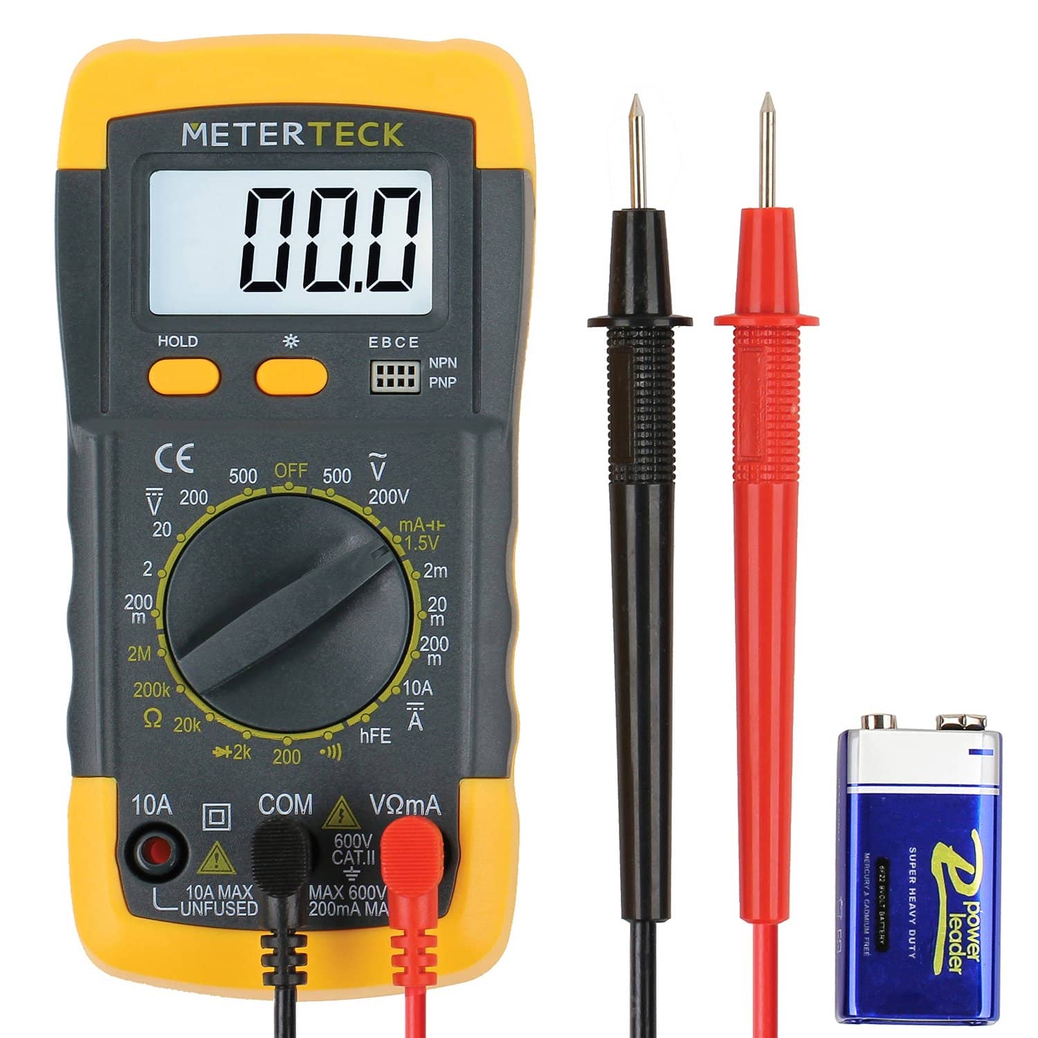
A multimeter is a portable, multifunctional electronic instrument designed to measure fundamental electrical properties with precision and adaptability. Combining analog and digital technologies, it serves as an essential tool for technicians, engineers, hobbyists, and quality assurance professionals across industries. Its versatility stems from the ability to integrate multiple measurement functions—voltage, current, and resistance—into a single device, often with additional features such as capacitance, frequency, and diode testing. The instrument’s design balances accuracy, durability, and ease of use, making it indispensable for troubleshooting circuits, verifying component specifications, and ensuring electrical safety.The core functionality of a multimeter relies on its ability to switch between measurement modes via a rotary selector, while its probes establish electrical contact with test points. Analog multimeters (using needle-based displays) and digital multimeters (featuring LCD screens) differ in resolution, response time, and user interface, each suited to specific applications. Below, the primary measurements—voltage, current, and resistance—are examined alongside their units, practical applications, and the technical distinctions between analog and digital implementations.
Fundamental Measurements and Their Applications
Multimeters perform three foundational electrical measurements, each critical for circuit analysis and component testing. These measurements are quantified in standardized units: voltage (V), current (A), and resistance (Ω), with real-world applications ranging from basic diagnostics to high-precision industrial testing.Voltage (V): Electrical potential difference between two points, measured in volts (V).Voltage Measurement
Current (A): Flow of electric charge, measured in amperes (A).
Resistance (Ω): Opposition to current flow, measured in ohms (Ω).
Voltage indicates the "push" or potential energy driving current through a circuit. Digital multimeters (DMMs) typically measure DC voltage with resolutions as fine as 0.1 mV, while analog meters offer a broader visual range for rapid assessments. Applications include:
Current Measurement
Current reflects the rate of electron flow, requiring the multimeter to be placed in series with the circuit to avoid damage. DMMs often limit current measurements to 10 A (or 20 A with external shunts) for safety, while analog meters may use a moving-coil mechanism for direct current (DC) readings. Key applications include:
Resistance Measurement
Resistance quantifies a component’s or circuit’s opposition to current, measured in ohms (Ω). Multimeters use an internal battery to apply a known voltage and measure the resulting current, with DMMs offering auto-ranging for efficiencies up to 40 MΩ. Applications include:
Analog vs. Digital Multimeters: Key Differences
The choice between analog and digital multimeters depends on factors such as accuracy requirements, environmental conditions, and budget. Below is a comparative analysis of their technical and practical distinctions:| Feature | Analog Multimeter | Digital Multimeter |
|---|---|---|
| Accuracy | Typically ±2–5% of full-scale reading, influenced by needle deflection and calibration drift. Suitable for approximate measurements. |
Ranges from ±0.5–1% of reading (basic models) to ±0.05% (high-end bench DMMs), with auto-calibration features. |
| Cost | Generally lower cost ($20–$100), ideal for hobbyists or educational settings where precision is secondary. |
Wider price range ($30–$2,000+), with professional-grade models offering advanced features like data logging and capacitance measurement. |
| Durability | Mechanical moving-coil meters are robust against EMI/RFI but vulnerable to physical shocks (e.g., dropped needles). |
Modern DMMs feature shockproof designs, IP-rated enclosures (e.g., IP67), and auto-ranging to prevent overload. |
| Response Time | Slower response (e.g., 1–2 seconds for needle stabilization), limiting use in dynamic circuits. |
Near-instantaneous readings (<100 ms for most measurements), essential for high-frequency or transient analysis. |
| Typical Use Cases |
|
|
Basic Controls and Measurement Procedure
A multimeter’s functionality is governed by its rotary selector switch, probes, and display, which must be configured correctly to avoid measurement errors or instrument damage. Below is a step-by-step guide to selecting a measurement mode, using a digital multimeter as an example:-
Power On and Display Verification
Activate the multimeter using the power switch or battery compartment. Ensure the LCD displays a zero reading (for voltage/resistance) or OL (overload) for current measurements. Modern DMMs may show a self-test screen upon startup.
-
Probe Connection
Insert the black probe into the COM (common) jack and the red probe into the VΩ jack (for voltage/resistance) or 10A jack (for current >200 mA). Secure connections prevent loose contacts, which can introduce noise or inaccurate readings.
-
Selector Switch Configuration
Rotate the rotary switch to the desired measurement mode:
- DC Voltage (V—): Align the switch with the V— symbol and select the appropriate range (e.g., 20V for a 9V battery). Auto-ranging DMMs eliminate manual range selection.
- AC Voltage (V~): Use the V~ setting for alternating current sources (e.g., wall outlets). Note that true RMS DMMs provide accurate readings for non-sinusoidal waveforms.
- DC Current (A—): Switch to the A— setting and choose a range exceeding the expected current (e.g., 200 mA for a LED circuit). For currents >200 mA, use the 10A jack and select 20A range.
- Resistance (Ω): Set the switch to Ω and select the highest range (e.g., 2 MΩ) initially, then adjust downward for precision (e.g., 2 kΩ for a 1 kΩ resistor). Ensure no power is applied to the circuit.
Key Components and Their Roles in Multimeter Operation
Multimeters rely on a combination of mechanical, electrical, and digital components to perform precise measurements across voltage, current, resistance, and other parameters. Each component plays a specialized role in ensuring accuracy, safety, and functionality. Understanding these elements—from the physical probes to the internal circuitry—enables users to select appropriate settings, interpret readings, and mitigate risks during testing. Proper handling of these components also extends the lifespan of the device while maintaining measurement integrity in varying environmental conditions.
Physical Components and Their Specific Functions
The design of a multimeter integrates several critical physical components, each contributing to signal acquisition, user interaction, and measurement processing. Below are the primary elements and their roles in the measurement workflow:
-
Probes (Test Leads)
Probes serve as the interface between the multimeter and the circuit under test, transmitting electrical signals for measurement. They typically consist of:- Probe Tips: Conductive metal tips (often banana or alligator-style) that establish contact with test points. Alligator clips ensure secure connections to components, while banana plugs facilitate quick attachment to multimeter jacks.
- Insulated Shafts: Prevent accidental short circuits or electric shocks by isolating the user from live conductors. High-quality probes use durable materials like PVC or silicone, with rated voltage/current limits (e.g., 600V CAT III for general electronics).
- Internal Wiring: Low-resistance cables (usually 0.1–0.5Ω) minimize signal loss during measurements. Shielded leads reduce electromagnetic interference (EMI) in noisy environments.
-
Display (LCD or LED)
The display converts processed electrical signals into human-readable values. Key features include:- Digital Displays: Use liquid crystal (LCD) or light-emitting diode (LED) technology to show numeric readings with resolutions ranging from 3.5 to 6.5 digits (e.g., 2000-count vs. 10,000,000-count). Higher resolutions improve precision for low-level signals (e.g., mV or µA measurements).
- Auto-Ranging vs. Manual Ranging: Auto-ranging displays automatically adjust scale (e.g., switching from 200mV to 2V), while manual models require user selection via the rotary switch. Auto-ranging reduces errors but may introduce latency in dynamic circuits.
- Graphical Indicators: Symbols such as battery icons, diode continuity beeps, or overload warnings (OL) provide immediate feedback on device status or measurement validity.
-
Rotary Switch (Function Selector)
The rotary switch determines the measurement type (voltage, current, resistance) and range, directly influencing the internal circuitry’s configuration. Key aspects include:- Positional Encoding: Mechanical or optical encoders detect switch positions, triggering the correct measurement mode. Misalignment (e.g., selecting 10A range for voltage) can damage the meter or cause false readings.
- Continuity and Diode Tests: Dedicated positions activate low-current paths (typically <1mA) to test component integrity without affecting circuit behavior.
- Auto-Polarity Detection: Some models automatically adjust for positive/negative voltage, while others require manual polarity selection (indicated by a "+" or "-" symbol).
-
Input Jacks (COM, VΩ, mA)
Jacks route signals to the appropriate internal pathways, ensuring correct measurement modes and protecting sensitive components. Standard configurations include:- COM (Common): The ground or reference point for all measurements. Always connects to the circuit’s negative terminal or common ground.
- VΩ (Voltage/Resistance): Used for voltage, resistance, capacitance, and continuity tests. Features high-impedance inputs (typically >10MΩ) to minimize loading effects on circuits.
- mA (Milliamperes): Dedicated for current measurements up to ~200–400mA. Higher-current ranges (10A) often require a separate jack or external shunt.
- 10A Jack (Optional): A separate port for current measurements exceeding the mA range, often with a fused input to prevent overload.
-
Battery Compartment
Powers digital multimeters (DMMs) and some analog models. Key considerations:- Battery Types: Typically 9V alkaline or lithium batteries, with lifespans varying by usage (e.g., 50–500 hours for continuous operation). Low battery voltage can cause erratic readings or display flickering.
- Auto-Power Down: Advanced models enter sleep mode after inactivity to conserve power, though this may delay response times.
- Backup Batteries (Optional): Some professional DMMs include rechargeable lithium-ion cells for extended field use.
Safe Probe Connection Procedures
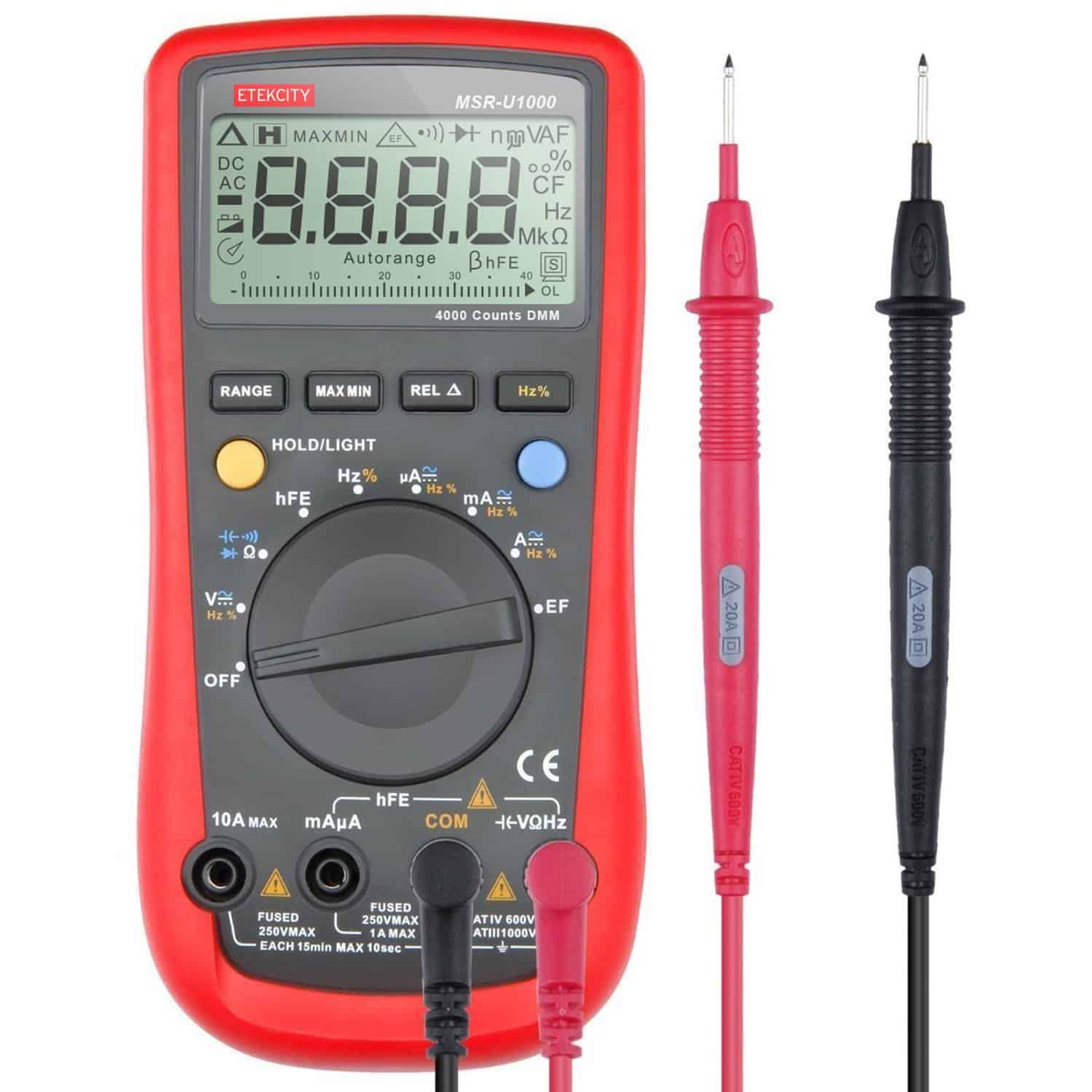
Proper probe connection is fundamental to accurate measurements and user safety. Incorrect polarity, jack selection, or physical handling can result in equipment damage, measurement errors, or electrical hazards. The following steps outline a standardized procedure for secure and safe connections:
-
Pre-Connection Checks
Before attaching probes, verify:- The multimeter is powered off (for analog models) or set to the correct range (digital models).
- Probes are undamaged, with intact insulation and secure connections to the multimeter jacks.
- The circuit under test is de-energized or isolated, unless measuring live voltage/current with appropriate precautions.
-
Polarity and Jack Selection
Follow these guidelines for correct probe placement:-
Voltage/Resistance Measurements:
- Connect the black probe to the COM jack (common ground).
- Connect the red probe to the VΩ jack for voltage or resistance tests.
- Ensure the rotary switch is set to the appropriate range (e.g., 200mV for DC voltage <200mV).
-
Current Measurements:
- Disconnect the circuit under test and insert the multimeter in series with the load (break the circuit and connect probes to the open terminals).
- Use the mA jack for currents <200mA and the 10A jack for higher currents (up to the meter’s limit).
- Set the rotary switch to the correct current range (e.g., 200mA for a 100mA load).
-
Continuity and Diode Tests:
- Use the VΩ jack and select the continuity or diode test mode on the rotary switch.
- For continuity, probes should beep or show a low resistance
Measurement Techniques and Best Practices
A multimeter is a versatile diagnostic tool essential for electrical troubleshooting, yet its effectiveness hinges on precise measurement techniques and adherence to safety protocols. Proper probe placement, scale selection, and calibration ensure accurate readings, while continuous monitoring versus snapshot measurements offer distinct advantages depending on the circuit behavior. Additionally, systematic troubleshooting of common errors—such as overload indications or erratic readings—minimizes diagnostic delays and prevents equipment damage.The following sections detail standardized procedures for measuring DC voltage, AC voltage, and resistance, alongside best practices for selecting measurement modes and interpreting results. Safety precautions are outlined in a structured format to mitigate risks, and troubleshooting workflows address frequent operational errors without reliance on visual aids.
Step-by-Step Measurement Procedures
Accurate multimeter readings depend on correct probe placement, functional settings, and environmental considerations. The following procedures apply to most digital multimeters (DMMs) and analog models, with adjustments for high-precision or specialized applications.DC Voltage Measurement
DC voltage is measured with the multimeter set to the DC voltage (V—) function, ensuring the black probe is connected to the COM (common) terminal and the red probe to the V/Ω terminal. For circuits with unknown voltage levels, begin with the highest range (e.g., 1000V) and decrement until the reading stabilizes within the display’s resolution. Probe placement must follow polarity conventions: the red probe connects to the positive terminal, and the black probe to the negative or ground reference. In live circuits, isolate the component under test to avoid parallel paths distorting readings.AC Voltage Measurement
AC voltage measurements require the multimeter to be set to AC voltage (V~), with probes connected identically to DC measurements. Unlike DC, AC measurements do not require polarity alignment, but the selected range must exceed the expected peak voltage (e.g., for a 120V AC circuit, use the 200V range). True RMS multimeters provide accurate readings for non-sinusoidal waveforms, while standard models may introduce errors in such cases. For safety, avoid measuring AC voltages exceeding the meter’s maximum rating, as arcing or internal damage can occur.Resistance Measurement
Resistance measurements necessitate a disconnected circuit to prevent parallel paths or power sources from skewing results. Set the multimeter to the resistance (Ω) function and select an appropriate range (e.g., 200Ω for low-resistance components like wires, 2MΩ for high-impedance sensors). Zeroing the meter is critical for accuracy: with probes shorted (touched together), adjust the zero-ohm (calibration) control until the display reads 0.00Ω. For components in situ, use two-wire Kelvin measurements (if available) to eliminate lead resistance errors. Avoid measuring resistance in live circuits, as even low voltages can produce false readings.
Continuous vs. Snapshot Measurements
The choice between continuous (live) and snapshot (single-shot) measurements influences diagnostic efficiency and data integrity. Each method serves distinct applications based on signal stability and troubleshooting requirements.Continuous Measurements
Continuous monitoring is ideal for dynamic signals, such as fluctuating voltages in power supplies, motor waveforms, or signal integrity tests in RF circuits. To capture transient events:
- Enable auto-ranging if available to adapt to voltage spikes.
- Use a data logger or oscilloscope for extended recording when the multimeter’s hold function is insufficient.
- For AC signals, note the peak-to-peak (Vpp) and average values, as RMS readings alone may mask distortions.
Snapshot Measurements
Snapshot readings are preferred for static components, such as verifying battery voltage, checking resistor values, or confirming DC bias points in amplifiers. Key advantages include:
- Reduced measurement noise from environmental interference (e.g., electromagnetic fields).
- Simpler documentation for compliance or baseline comparisons.
- Lower risk of probe movement artifacts during prolonged contact.
Scenario Applications
- Fluctuating signals: Use continuous mode to diagnose power supply ripple, motor brush arcing, or solar panel output variations.
- Static components: Snapshot mode suffices for verifying resistor networks, diode forward voltage, or capacitor charge/discharge curves.
Safety Precautions for Multimeter Use
Electrical measurements carry inherent risks, including shock hazards, equipment damage, and data inaccuracies. The following table categorizes common hazards, associated risks, and mitigation strategies to ensure safe operation.
Hazard Risk Mitigation Live Circuit Measurement Without Isolation Electric shock, equipment damage, or fire. - Power off the circuit or use an isolation transformer.
- Verify de-energization with a non-contact voltage tester.
- Use a differential probe or insulated tools for high-voltage measurements.
Skin Contact with Probes Electrical shock, burns, or incorrect measurement paths. - Hold probes by their insulated handles.
- Use probe covers or alligator clips for hands-free operation.
- Avoid touching probe tips or exposed metal parts.
Incorrect Probe Placement or Polarity Damaged meter, inaccurate readings, or component failure. - Double-check probe connections (COM to ground/negative, V/Ω to positive/test point).
- For AC measurements, ensure probes are not shorted to ground.
- Use reverse polarity protection (if available) for DC measurements.
Exceeding Multimeter Ratings Internal damage, blown fuses, or inaccurate readings. - Select the highest voltage range for unknown circuits.
- Use current shunts or current probes for measurements exceeding 10A.
- Replace blown fuses immediately and identify the root cause.
Measuring Resistance in Live Circuits False readings, component damage, or short circuits. - Disconnect power sources and discharge capacitors before measurement.
- Use a dedicated resistance measurement mode or ohmmeter.
- For in-circuit resistance, use a Kelvin (4-wire) measurement if supported.
Environmental Interference (EMF, Humidity) Noisy readings, reduced accuracy, or equipment corrosion. - Perform measurements in a shielded environment or away from power lines.
- Use twisted-pair cables or shielded probes for high-frequency signals.
- Store the multimeter in a dry, temperature-controlled space.
Troubleshooting Common Multimeter Errors
Operational errors in multimeters often stem from user misconfiguration, environmental factors, or component limitations. The following diagnostic steps address frequent issues without visual aids, emphasizing systematic verification.Overload Indication ("OL")
An "OL" (overload) display occurs when the input exceeds the selected range or the meter’s maximum rating. To resolve:
1. Increase the range to a higher voltage/current setting (e.g., from 20V to 200V).
2. Verify probe connections: Ensure probes are not shorted or connected to incorrect terminals (e.g., current probe on voltage input).
3. Check for fused components: Replace blown fuses and inspect for physical damage to the meter.
4. Isolate the circuit: For high-voltage measurements, use a voltage divider or high-voltage probe.
5. Test with a known reference: Measure a stable voltage source (e.g., battery) to confirm meter functionality.Incorrect or Erratic Readings
Erratic readings may result from loose probe contacts, environmental noise, or internal faults. Follow these steps:
1. Inspect probe connections: Ensure probes are securely attached to the meter and test points. Clean oxidized contacts with isopropyl alcohol.
2. Verify auto-ranging operation: Disable auto-range if enabled, then manually select a range close to the expected value.
3. Check for parallel paths: In resistance measurements, ensure no other components are creating
Advanced Features and Specialized Uses of Multimeters
Multimeters extend beyond basic voltage, current, and resistance measurements through advanced functionalities that cater to specialized applications in diagnostics, research, and industrial testing. These features—such as diode testing, capacitance measurement, frequency analysis, and temperature sensing—rely on integrated circuits, specialized probes, and precise calibration to deliver accurate results. Professional fields leverage these capabilities to troubleshoot complex systems, validate performance, and ensure safety in environments where standard measurements are insufficient. Below, the internal mechanisms enabling these features are explored, alongside real-world applications in automotive, renewable energy, and electronics repair.
Diode Testing and Semiconductor Analysis
Diode testing is a critical function for evaluating semiconductor components, where the multimeter applies a small voltage (typically 2.8V) to determine forward voltage drop and continuity. The internal circuit includes a current-limited voltage source and a comparator to distinguish between forward-biased and reverse-biased states, displaying readings in millivolts or indicating open/short conditions. For transistors, some advanced multimeters measure hFE (current gain) by injecting a base current and measuring collector-emitter current, though dedicated transistor testers offer higher precision.Applications in Professional Fields:
- Automotive Diagnostics: Identifying faulty diodes in alternators or rectifier bridges to diagnose charging system failures.
- PCB Repair: Verifying diode orientation and integrity in power supply circuits or signal pathways before soldering replacements.
- Solar Panel Testing: Assessing bypass diodes in photovoltaic modules to detect shading-induced faults or degradation.
Key Mechanism:
The diode test circuit employs a constant-current source (typically 0.5–1 mA) to avoid damaging sensitive components. Forward voltage readings (e.g., 0.6–0.7V for silicon diodes) confirm proper operation, while infinite resistance in reverse bias indicates an open circuit.Capacitance Measurement and Transient Response Analysis
Capacitance measurement in multimeters utilizes a charge/discharge method, where the device applies a known voltage to the capacitor and measures the time required to charge or discharge to a reference level. The internal oscillator generates a square wave, and the multimeter’s microcontroller calculates capacitance using the formula:
C = (t × I) / V, where t is discharge time, I is the discharge current, and V is the reference voltage. High-end models incorporate auto-zeroing to compensate for parasitic capacitance in probe leads and the meter itself.Specialized Applications:
- Power Electronics: Testing electrolytic capacitors in DC-link circuits to detect leakage or degradation before failure.
- Audio Equipment: Measuring filter capacitors in amplifiers to ensure signal integrity and reduce noise.
- Embedded Systems: Verifying decoupling capacitors on PCB prototypes to prevent voltage ripple in microcontroller power rails.
Limitations and Workarounds:
Standard multimeters struggle with high-frequency capacitance (e.g., ceramic capacitors >1 MHz) due to probe inductance. For accurate results, LCR meters or oscilloscope-based methods are preferred, though multimeters suffice for most DC-coupled applications.Frequency and Duty Cycle Analysis
Frequency measurement in multimeters relies on edge detection circuits that count rising/falling edges of an input signal over a fixed time interval. The internal comparator triggers a counter, and the microcontroller divides the count by the time base to compute frequency (Hz). Advanced models also measure duty cycle by comparing pulse width to period, using a second counter for high-resolution timing. Some units include auto-ranging for signals up to 100 MHz, though dedicated frequency counters offer higher precision (±0.01%).Professional Use Cases:
- Motor Control Systems: Diagnosing PWM signal integrity in variable-frequency drives (VFDs) to identify misfiring or overshoot.
- Telecommunications: Verifying carrier frequencies in RF modules or testing clock signals in digital circuits.
- Renewable Energy: Monitoring inverter output frequencies in grid-tied solar systems to ensure compliance with utility standards (e.g., 50/60 Hz ±0.5 Hz).
Internal Architecture:
Frequency inputs often include high-impedance buffers (1 MΩ) to minimize loading effects on the circuit under test. Some multimeters use oversampling to reduce jitter errors, averaging multiple measurements for stability.Temperature Sensing with Thermocouple and RTD Support
Temperature measurement in multimeters is achieved via thermocouple inputs (e.g., Type K, J, T) or resistance temperature detectors (RTDs), where the device applies a constant current and measures the resulting voltage drop. For thermocouples, the multimeter compensates for cold-junction temperature using an internal sensor, applying the Seebeck effect formula:
V = α × (T₁ – T₂), where α is the thermoelectric coefficient. RTD measurements use a 4-wire configuration to eliminate lead resistance errors, with the multimeter calculating temperature via the Callendar-Van Dusen equation.Industrial and Research Applications:
- Automotive: Monitoring exhaust gas temperatures (EGT) or battery thermal management systems (BTMS) in electric vehicles.
- HVAC Systems: Diagnosing refrigerant superheat/subcooling in AC units by measuring evaporator/condenser temperatures.
- Semiconductor Manufacturing: Tracking junction temperatures in power transistors during load testing to prevent thermal runaway.
Precision Considerations:
Thermocouple multimeters typically offer ±1°C accuracy at room temperature, degrading to ±2°C at extremes. For laboratory use, precision RTD multimeters with 0.1°C resolution are preferred, often paired with ice-point references for calibration.Comparison of Multimeter Types: Basic vs. Auto-Ranging vs. Benchtop/Industrial
The following table outlines the distinguishing features of multimeter categories, emphasizing capabilities critical for different professional environments. Auto-ranging models automate range selection, reducing user error, while benchtop/industrial units prioritize durability, data logging, and specialized measurements.
Feature Basic Multimeter Auto-Ranging Multimeter Benchtop/Industrial Multimeter Display 3.5-digit LCD, manual range selection 3.5–4.5-digit LCD/LED, auto-ranging with hold function 5.5–8-digit LCD, backlit, graphing capabilities (e.g., Fluke 87V) Input Impedance 10 MΩ (DCV), 1 MΩ (ACV) 10 MΩ (DCV), 1 MΩ (ACV), low-Z options for current 10 GΩ (DCV), 10 MΩ (ACV), ultra-low leakage for high-resistance measurements Data Logging None Limited (USB/Bluetooth on mid-range models) Built-in memory, cloud integration, or external logging via GPIB/LAN Specialized Measurements Diode, continuity, basic capacitance (some models) Frequency, duty cycle, temperature (thermocouple/RTD), advanced capacitance LCR, temperature profiling, waveform capture, partial discharge (PD) testing Durability Rubberized housing, drop resistance (e.g., IEC 61010-1) IP67-rated, vibration-resistant, CAT III/IV compliance Military-grade (MIL-STD-810), explosion-proof (ATEX/IEEx), wide temperature range (-40°C to +85°C) Connectivity None or basic USB USB/Bluetooth, Wi-Fi (some models) GPIB, LAN, RS-232, Modbus, OPC UA for SCADA integration Calibration Interval Annual (user-serviceable) 
Troubleshooting and Maintenance of Digital Multimeters
Digital multimeters (DMMs) are precision instruments whose accuracy and reliability depend on proper calibration, maintenance, and troubleshooting of malfunctions. Without systematic upkeep, even high-end models may exhibit drifting readings, reduced performance, or complete failure. This section provides structured guidance on calibration procedures, diagnosing common faults, preventive maintenance, and selecting compatible replacement components to ensure long-term operational integrity.
Calibration Procedures for Digital Multimeters
Calibration ensures a multimeter’s measurements align with standardized reference values, mitigating errors caused by component drift, environmental factors, or usage wear. The process typically involves comparing the DMM’s readings against a known-accurate reference (e.g., a calibration jig or traceable resistor) and adjusting internal settings via calibration menus or trimmer potentiometers. Below is a step-by-step guide for basic calibration, applicable to most digital multimeters with built-in calibration features.Tools and Equipment Required
A dedicated calibration setup typically includes:
- Calibration jig: A precision device generating stable reference voltages (e.g., 1.018V for diode testing, 1000Ω for resistance).
- Reference resistor: A traceable resistor (e.g., 100Ω, 1kΩ, 10kΩ) with certified accuracy (±0.01% or better).
- Certified voltage source: For DC voltage calibration (e.g., a Fluke 5720A or similar).
- Oscilloscope or data logger: Optional, for verifying AC signal accuracy.
- Calibration software: If the DMM supports PC-based calibration (e.g., via USB or RS-232).
- Isolation transformer or battery-powered supply: To avoid ground loops during calibration.
Step-by-Step Calibration Process
1. Preparation and Safety Checks
Ensure the multimeter is powered off and disconnected from all circuits. Verify the calibration jig and reference components are within their specified temperature range (typically 20–25°C) to avoid thermal-induced errors. Use insulated tools to handle probes and connections.2. Initial Self-Test
Power on the DMM and run any built-in self-diagnostic routines (accessible via menu options like "Self-Test" or "Calibration Mode"). Record baseline readings for DC voltage, AC voltage, resistance, and continuity at key ranges (e.g., 200mV, 2V, 20V, 200V; 200Ω, 2kΩ, 20kΩ).3. DC Voltage Calibration
- Connect the calibration jig’s output to the DMM’s input terminals (compliance with the jig’s polarity requirements).
- Select the appropriate DC voltage range (e.g., 2V for a 1.018V reference).
- Adjust the DMM’s internal trimmer (if accessible) or follow on-screen prompts to match the jig’s reference value. For software-assisted calibration, input the reference value into the DMM’s calibration menu and allow the device to auto-adjust.
- Repeat for additional ranges (e.g., 20V, 200V) if the jig supports them.
4. Resistance Calibration
- Connect the reference resistor (e.g., 100Ω) across the DMM’s input terminals.
- Select the 200Ω range and adjust the DMM’s resistance trimmer (often labeled "Zero Ω" or "Cal R") until the reading matches the resistor’s certified value (±0.1% tolerance).
- Verify accuracy at higher ranges (e.g., 2kΩ, 20kΩ) by switching ranges and recalibrating if necessary.
5. AC Voltage and Current Calibration
- For AC voltage, use a calibrated AC source (e.g., 1V RMS at 60Hz) and adjust the DMM’s AC gain trimmer or follow software prompts.
- For current calibration, employ a current shunt or calibrated load resistor. Apply a known current (e.g., 100mA) and adjust the DMM’s current range offsets if provided.
6. Diode and Continuity Calibration
- Use the calibration jig’s diode test output (typically 1.018V) to verify the DMM’s forward-voltage measurement. Adjust the diode offset trimmer if available.
- For continuity, short the input terminals and ensure the DMM beeps or displays 0Ω within specifications.
7. Final Verification
- Reconnect the calibration jig and perform a full-range sweep (DC/AC voltage, resistance, current) to confirm consistency.
- Record calibration dates, reference values, and any adjustments made in the DMM’s log or a maintenance spreadsheet.
- If the DMM lacks built-in calibration features, consult the manufacturer’s service manual for external calibration procedures (e.g., adjusting PC-board trimmers).
Diagnosing Common Multimeter Malfunctions
Multimeters may exhibit symptoms of degradation or failure due to mechanical wear, electrical stress, or user error. Systematic diagnosis involves visual inspection, self-tests, and comparative measurements with a known-good device. Below are structured approaches to identifying and resolving frequent issues.Visual Inspection and Preliminary Checks
- Dead or Weak Battery: Symptoms include erratic displays, slow response, or automatic shutdown. Replace the battery (typically 9V or CR2032) and verify functionality.
- Loose or Corroded Connections: Inspect probe tips, binding posts, and internal solder joints for oxidation or poor contact. Clean terminals with isopropyl alcohol and a non-metallic brush.
- Damaged Probes: Cracked insulation, bent tips, or exposed wires can cause short circuits or inaccurate readings. Replace probes if resistance exceeds 0.1Ω or insulation is compromised.
- Display Issues: Flickering or blank screens may indicate a failing LCD module, loose ribbon cable, or power supply failure. Test with a known voltage source to isolate the fault.
Self-Test and Comparative Measurements
1. Self-Test Routine
Most DMMs include a self-test function (accessed via a dedicated button or menu). Run the test and note any error codes (e.g., "Low Battery", "ADC Fault", "Fuse Open"). Refer to the manual for code interpretations.2. Comparative Resistance Measurement
- Measure a known resistor (e.g., 1kΩ) with the suspect DMM and a calibrated reference meter.
- Discrepancies >±0.5% suggest ADC (analog-to-digital converter) drift or input circuit issues.
3. Voltage/Current Offset Check
- Connect the DMM to a stable reference (e.g., a bench power supply set to 5V).
- Compare readings with a secondary meter. Systematic offsets (e.g., +0.1V) indicate calibration drift or input amplifier problems.
4. Probe and Input Circuit Testing
- Measure the resistance of probes (should be <0.1Ω for short leads). High resistance suggests internal wiring faults.
- Check for continuity between the DMM’s input terminals and ground (should be open). A short indicates internal damage.
Common Malfunctions and Corrective Actions
Symptom Possible Cause Diagnostic Steps Solution Drifting Readings (e.g., voltage fluctuates ±0.05V) ADC drift, temperature effects, or aging components Compare with reference meter; check ambient temperature stability Recalibrate; replace DMM if drift persists beyond calibration Overload or "OL" Display on Low Voltages Faulty input fuse, damaged input protection circuit Inspect fuse (replace if blown); measure input resistance (should be >10MΩ) Replace fuse (use manufacturer-specified rating); service input circuit if resistance is low No Display or Random Characters Dead battery, LCD failure, or loose connections Replace battery; check LCD contrast and backlight; inspect ribbon cable Replace battery; replace LCD module if defective; resolder connections Probes Shorting or High Resistance Damaged probe wiring, corroded tips, or internal short Measure probe resistance; inspect for physical damage Replace probes; clean or replace binding posts Incorrect AC Measurements (e.g., 10% error) Faulty AC input filter or ADC FAQ
What is a multimeter used for?
A multimeter is a versatile electronic tool used to measure voltage, current, and resistance in electrical circuits. It can also test continuity, capacitance, and sometimes temperature or frequency, making it essential for troubleshooting, repairs, and installations in electronics and electrical work.
What is a multimeter tester?
A multimeter tester is another name for a multimeter—a handheld device that combines multiple measurement functions (voltage, current, resistance, etc.) into a single unit. It’s called a "tester" because it verifies electrical properties and identifies faults in circuits or components.
What is a multimeter and how does it work?
A multimeter is a portable device that measures electrical values like voltage (AC/DC), current, and resistance. It works by sending a small test current through the circuit and displaying readings on a digital or analog screen, with probes connected to the component or circuit being tested.
What is a multimeter tool?
A multimeter tool is a handheld electronic instrument used by electricians, technicians, and hobbyists to diagnose and test electrical systems. It combines features of an ammeter, voltmeter, and ohmmeter, allowing precise measurements for safety checks, circuit analysis, and equipment repairs.
What is a multimeter used for in HVAC?
In HVAC systems, a multimeter is used to test electrical connections, check motor windings for continuity or shorts, measure voltage at transformers or capacitors, and diagnose control board issues. It helps ensure safe operation and identifies faults in wiring, thermostats, or compressors.
What is a multimeter for a car?
In cars, a multimeter is used to check battery voltage, test alternator output, diagnose starter motor or solenoid issues, and inspect wiring for shorts or breaks. It’s also useful for troubleshooting sensors (like oxygen or temperature sensors) and verifying fuse or relay functionality.
-
Voltage/Resistance Measurements:
Leave a Comment
Comments are moderated before appearing. The data you submit is processed according to the Privacy Policy of Voltefac.