| CO₂ Laser |
9000–11000 (10.6 µm typical) |
- Sheet metal cutting (automotive, aerospace).
- Wood and plastic engraving.
- Welding of non-metals (e.g.,
Material-Specific Applications and Suitability in Laser Beam Machining
Laser Beam Machining (LBM) demonstrates material-specific versatility, enabling precision processing across metals, ceramics, polymers, and composites. The compatibility of a material with LBM depends on its optical, thermal, and mechanical properties, which dictate laser absorption, heat distribution, and machinability. While ductile metals like aluminum and titanium require adjustments in pulse frequency and beam focus to mitigate thermal distortion, brittle materials such as glass or quartz necessitate controlled energy delivery to prevent cracking. Industrial sectors leverage these adaptations—from aerospace for titanium alloy cutting to medical devices for polymer micromachining—where LBM’s non-contact nature and minimal thermal affected zones (TAZ) provide critical advantages over traditional methods like mechanical cutting or electrical discharge machining (EDM).
Categorization of Materials by Laser Compatibility and Machining Characteristics
Materials machined via LBM are classified based on their interaction with laser energy, primarily governed by reflectivity, thermal conductivity, melting point, and thermal expansion coefficients. Metals, ceramics, polymers, and composites each exhibit distinct behaviors under laser irradiation, influencing parameter selection (e.g., wavelength, pulse duration, power density). The following table summarizes key material groups, their laser compatibility, and typical applications:
| Material Category |
Key Properties Affecting LBM |
Laser Compatibility |
Industrial Applications |
Preferred Laser Types |
|---|
| Metals (Ductile) |
- High thermal conductivity (e.g., copper, aluminum)
- Moderate reflectivity (varies by wavelength; e.g., titanium absorbs CO₂ poorly but excimer lasers effectively)
- Thermal distortion risk due to high heat capacity
|
High (with parameter optimization for heat management) |
Aerospace (titanium), automotive (steel), electronics (copper) |
Fiber (Yb:YAG), CO₂, Nd:YAG |
| Ceramics (Brittle) |
- Low thermal conductivity (e.g., alumina, zirconia)
- High melting points (e.g., tungsten carbide)
- Cracking risk from thermal shock
|
Moderate to high (requires ultra-short pulses or controlled heating) |
Medical implants (bioceramics), electronics (substrate drilling) |
Ultrafast lasers (fs/ps), CO₂ |
| Polymers (Thermoplastics/Elastomers) |
- Low thermal conductivity (rapid localized heating)
- High absorption at specific wavelengths (e.g., CO₂ for polyimide)
- Degradation risk at excessive temperatures
|
High (for precision micromachining) |
Medical devices (catheters), microelectronics (flexible circuits) |
CO₂, excimer, fiber lasers |
| Composites (Fiber-Reinforced) |
- Heterogeneous thermal properties (matrix vs. fiber)
- Delamination risk from uneven heating
- Carbon fiber absorbs near-IR strongly; glass fiber requires UV
|
Moderate (parameter tuning critical for fiber integrity) |
Aerospace (CFRP), automotive (lightweight panels) |
Ultrafast lasers, CO₂ |
Note: Material reflectivity inversely correlates with laser absorption efficiency. For instance, aluminum reflects ~90% of CO₂ laser energy but absorbs >90% of Nd:YAG (1.06 µm) radiation, necessitating wavelength selection based on material spectra.
Challenges and Adaptations for Brittle vs. Ductile Materials
The primary distinction between machining brittle (e.g., glass, quartz) and ductile (e.g., aluminum, titanium) materials lies in their response to thermal and mechanical stresses induced by laser energy. Brittle materials lack plasticity, making them susceptible to microcracking or thermal shock, while ductile metals risk heat-affected zone (HAZ) expansion or residual stress buildup. Adaptations include:- For Brittle Materials (Glass, Ceramics, Quartz): -
Pulse Duration Optimization:
Ultra-short pulses (femtosecond to picosecond) minimize heat diffusion, reducing thermal damage. For example, femtosecond lasers achieve crack-free drilling in fused silica with pulse energies as low as 1 µJ.
-
Beam Focus and Spot Size:
Tight focusing (small spot diameters, <50 µm) increases peak power density, enabling precise ablation without lateral heat spread. Quartz machining often uses spot sizes of 20–30 µm for micro-optics.
-
Assisted Gas Jets:
High-pressure air or nitrogen cools the ablation zone, mitigating thermal gradients. In glass micromachining, assist gases can reduce recast layer formation by up to 60%.
-
Pre-Heating or Annealing:
Controlled pre-heating (e.g., 300–500°C for borosilicate glass) reduces thermal shock by equalizing temperature gradients across the material.
- For Ductile Metals (Aluminum, Titanium, Copper):
Thermal Management via Pulse Parameters:
Lower pulse frequencies (e.g., 10–50 kHz) allow heat dissipation between pulses, preventing melt pool instability. Titanium machining often uses 20 kHz with pulse durations of 100–500 µs.
-
Hybrid Cooling Techniques:
Cryogenic cooling (e.g., liquid nitrogen) or adaptive gas flows (e.g., oxygen for oxidation-assisted cutting) enhance heat extraction. In aluminum, oxygen-assisted cutting increases cutting speeds by 30–40%.
-
Beam Defocus Strategies:
Slight defocusing (e.g., +0.5 mm) broadens the heat-affected zone, reducing residual stresses in thick-section metals like Inconel 718.
-
Material-Specific Wavelength Selection:
Aluminum’s high reflectivity to CO₂ lasers (10.6 µm) necessitates Nd:YAG (1.06 µm) or fiber lasers (1.07 µm), which are absorbed more efficiently.
Key Trade-off: Brittle materials prioritize minimizing heat input, while ductile metals focus on controlling heat distribution to avoid distortion.
Adjustment of Laser Parameters for Precision Cutting vs. Deep Engraving
Laser parameters—power density, pulse frequency, beam focus, and scan speed—are dynamically adjusted based on the desired outcome: precision cutting (e.g., kerf widths <50 µm) or deep engraving (e.g., depths >1 mm). The following table contrasts parameter settings for these applications across material classes:
| Parameter |
Precision Cutting (e.g., Microelectronics, Medical Stents) |
Deep Engraving (e.g., Aerospace Marking, Industrial Labels) |
|---|
| Power Density (W/cm²) |
10⁶–10⁸ (ultra-short pulses for ablation without melting) |
10⁴–10⁶ (continuous or long-pulse for controlled melting/evaporation) |
| Pulse Frequency (Hz) |
100 kHz–1 MHz (high repetition for fine features) |
1–50 kHz (lower frequency allows deeper penetration per pulse

Laser Beam Machining Techniques and Variations
Laser Beam Machining (LBM) encompasses a diverse range of high-precision material processing techniques, each tailored to specific industrial requirements. The selection of technique—whether cutting, drilling, welding, or marking—depends on material properties, dimensional tolerances, and surface integrity demands. Advances in laser technology, including ultrafast lasers and adaptive beam delivery systems, have expanded the scope of LBM, enabling applications from microelectronics to aerospace manufacturing. This section examines the operational principles, comparative performance, and procedural nuances of conventional and advanced LBM techniques, alongside their role in automated manufacturing environments.
Common Laser Beam Machining Techniques and Their Operational Setups
Laser Beam Machining techniques are categorized based on their primary function: material removal, joining, or surface modification. Each technique employs distinct laser parameters, assist gases, and motion control systems to achieve the desired outcome.Laser Cutting
Laser cutting involves the focused delivery of high-power laser beams to melt, vaporize, or burn material along a predefined path. The process is classified into four primary modes:
Fusion Cutting: Uses a reactive gas (e.g., oxygen) to oxidize the material, facilitating material removal via molten slag expulsion. Common in mild steel and stainless steel processing.
Melt-and-Blow Cutting: Employs inert gases (e.g., nitrogen) to blow away molten material, ideal for non-ferrous metals like aluminum and copper.
Sublimation Cutting: Utilizes high-power CO₂ or fiber lasers to vaporize material directly, minimizing heat-affected zones (HAZ). Suitable for polymers and thin metals.
Cold Cutting: Achieved with ultrafast lasers (e.g., picosecond or femtosecond), where material is ablated without thermal damage, enabling precision cuts in delicate materials like silicon wafers or medical implants.Laser Drilling
Laser drilling employs pulsed or continuous-wave lasers to create holes via percussion, trepanning, or helical drilling. Key methods include:
Percussion Drilling: Short, high-energy pulses vaporize material, forming a hole. Used in printed circuit boards (PCBs) and turbine blades.
Trepanning Drilling: A circular path around the hole perimeter removes material incrementally, reducing debris ejection. Common in aerospace components.
Helical Drilling: Combines rotational and axial motion to create deep, high-aspect-ratio holes with minimal taper, critical for fuel nozzles and medical devices.Laser Welding
Laser welding fuses materials via localized melting, with techniques differentiated by power density and interaction time:
Conduction-Limited Welding: Low-power lasers (e.g., <1 kW) create shallow welds with minimal penetration, used in microelectronic soldering.
Keyhole Welding: High-power lasers (e.g., >1 kW) generate a vaporized capillary, enabling deep penetration welds in thick sections (e.g., automotive chassis).
Hybrid Laser-Arc Welding: Combines laser and arc welding to improve weld pool stability and reduce distortion in large-scale structures.Laser Marking and Engraving
These techniques modify surface properties for identification or aesthetic purposes:
Ablation Marking: Uses pulsed lasers to remove material layers, creating permanent marks (e.g., serial numbers on tools).
Annealing Marking: Alters material microstructure via controlled heating, producing color changes without material removal (e.g., barcodes on pharmaceutical packaging).
Color Marking: Employed on metals to induce oxidation for decorative or functional markings (e.g., titanium implants).
Comparative Analysis: Conventional vs. Advanced Laser Machining Methods
The evolution of laser technology has introduced trade-offs between precision, thermal effects, and processing speed. Below is a comparative assessment of conventional (e.g., CO₂, Nd:YAG) and advanced (e.g., ultrafast femtosecond) lasers in key performance metrics:
| Parameter | Conventional Lasers (CO₂, Nd:YAG) | Advanced Lasers (Femtosecond, Picosecond) |
|---|
| Precision | Limited by heat diffusion (~tens of micrometers). | Sub-micron resolution due to non-linear absorption. |
| Heat-Affected Zone (HAZ) | Significant thermal damage, warping, or recrystallization. | Minimal to negligible HAZ; cold processing. |
| Surface Finish | Roughness (Ra ~5–20 µm) due to melting and re-solidification. | Smooth finishes (Ra < 0.1 µm) with minimal burr formation. |
| Processing Speed | High for bulk material removal (e.g., cutting steel). | Slower for bulk removal but optimal for micro-machining. |
| Material Suitability | Metals, polymers, wood, and ceramics with high reflectivity. | Transparent materials (e.g., glass, sapphire) and heat-sensitive substrates. |
| Cost and Complexity | Lower initial cost; mature technology. | Higher capital expenditure; requires precise beam delivery. |
Key Considerations for Selection:
Thermal Sensitivity: Ultrafast lasers are preferred for electronics, optics, and biomedical devices where thermal distortion is critical.
Throughput Requirements: Conventional lasers dominate high-volume industrial cutting (e.g., automotive body panels).
Material Properties: High-reflectivity metals (e.g., copper, aluminum) benefit from wavelength-matched lasers (e.g., fiber lasers at 1 µm).
Procedural Steps for Laser Micro-Machining with Minimal Collateral Damage
Laser micro-machining demands meticulous control over beam parameters, alignment, and environmental conditions to avoid unintended material alterations. The following steps outline a standardized approach:1. System Alignment and Calibration
Beam Path Optimization: Ensure collimated and focused beams using kinematic mounts and interferometric alignment tools.
Focal Positioning: Adjust the focal plane to balance energy density (higher at focus for ablation, lower for annealing).
Assist Gas Integration: Select gases (e.g., nitrogen for oxidation prevention, helium for heat dissipation) based on material reactivity.2. Parameter Optimization
Pulse Duration: Shorter pulses (femtosecond range) reduce thermal diffusion; longer pulses (millisecond) increase depth but risk HAZ.
Repetition Rate: Higher rates improve surface finish but may induce cumulative heating in metals.
Scan Strategy: Utilize vector or raster patterns to distribute heat evenly and prevent localized overheating.3. Real-Time Monitoring and Feedback
Acoustic Emission Sensors: Detect material ablation onset to adjust power dynamically.
Thermal Imaging: Monitor surface temperature to prevent exceeding material thresholds (e.g., 300°C for polymers).
Debris Management: Employ suction systems or inert gas curtains to clear ablation byproducts from the interaction zone.4. Post-Processing Inspection
Dimensional Verification: Use optical profilometry or coordinate measuring machines (CMMs) to validate tolerances.
Surface Integrity Analysis: Employ scanning electron microscopy (SEM) to assess microstructural changes.Mitigation Strategies for Collateral Damage:
Pre-Heating: For brittle materials (e.g., ceramics), gradual heating reduces thermal shock.
Hybrid Cooling: Combine cryogenic cooling with laser pulses to limit HAZ in heat-sensitive alloys.
Adaptive Optics: Dynamically correct beam distortions using deformable mirrors for high-precision applications.
Role of Beam Delivery Systems in Automated and High-Speed Machining
Beam delivery systems determine the flexibility, speed, and precision of LBM processes. Modern systems integrate optics, motion control, and automation to meet industrial demands:1. Fiber-Optic Delivery
Advantages: Compact, flexible, and immune to electromagnetic interference (EMI). Enables integration into robotic arms for 3D machining.
Applications: Medical device fabrication, additive manufacturing (e.g., laser powder bed fusion), and automated cutting cells.
Limitations: Attenuation at certain wavelengths (e.g., CO₂ lasers require hollow-core fibers).2. Galvo Scanners
Operational Principle: Uses rotating mirrors to deflect the beam at high speeds (up to 100 m/s), enabling 2D and 3D vector scanning.
Key Features:
Field Size: Up to 500 × 500 mm² with high resolution (e.g., 25 µm spot size).
Dynamic Focusing: Adjustable focal lengths via adaptive optics for variable-depth machining.
Applications: PCB drilling, micro-engraving, and rapid prototyping.3. Flying Optics Systems
Configuration: Mounts scanning mirrors directly on the workpiece or a moving gantry, reducing mechanical inertia.
Benefits: Enables high-speed marking (e.g., >10 m/s) and large-area processing without repositioning.
Use Cases: Automotive part coding, solar panel scribing, and roll-to-roll manufacturing.4. Beam Sh
Equipment and System Components in Laser Beam Machining
Laser Beam Machining (LBM) relies on a precisely engineered system integrating optical, mechanical, and control subsystems to achieve high-precision material processing. The performance of LBM is directly influenced by the selection and integration of critical components, including laser resonators, beam delivery systems, motion control units, and auxiliary peripherals. Industrial-grade systems must balance power output, beam quality, and thermal management to meet application-specific demands, while adherence to safety protocols ensures operator protection and system longevity. The efficiency and precision of LBM operations depend on the interplay between hardware components and software-driven controls. Below are the core elements of a laser machining system, their functional roles, and the technical specifications governing their selection.
Critical Components of a Laser Machining System
The architecture of an LBM system comprises three primary functional domains: laser generation, beam manipulation, and process control. Each domain incorporates specialized components designed to optimize energy delivery, spatial accuracy, and material interaction.Laser Resonators
The resonator is the heart of the laser system, where the gain medium (e.g., CO₂, fiber, or solid-state crystals) is excited to produce coherent light. Key considerations include:
Gain Medium: Determines wavelength (e.g., 10.6 µm for CO₂, 1.06 µm for Nd:YAG), absorption characteristics, and thermal management requirements.
Optical Cavity Design: Influences beam divergence, mode structure (TEM₀₁ for high quality), and output stability.
Power Scaling: Industrial resonators range from 500W to 20kW for CO₂ lasers, with fiber lasers achieving 1kW to 50kW outputs, depending on application (cutting, welding, or marking).Beam Delivery Systems
These components ensure precise energy transmission from the resonator to the workpiece. Key elements include:
Beam Expanders: Adjust focal spot size and divergence to match material thickness and cutting speed (e.g., 2x–10x expansion for fine detailing).
Mirrors and Focusing Optics: Typically use copper-coated zinc-selenide (ZnSe) mirrors for CO₂ lasers or dielectric-coated mirrors for fiber lasers, with focal lengths of 50mm–200mm for industrial cutting heads.
Galvanometer or Scanning Systems: Enable dynamic beam steering for 2D/3D contouring, with resonance frequencies up to 10kHz for high-speed marking.Motion Control Systems
Precision positioning is critical for maintaining tolerances in LBM. Components include:
CNC Controllers: Integrate servo motors with closed-loop feedback (e.g., Heidenhain or Siemens Sinumerik) for sub-micron accuracy.
Linear Guides and Ball Screws: Ensure minimal backlash in X-Y-Z axes, with 0.001mm repeatability in high-end systems.
Workpiece Handling: Includes vacuum tables, rotary axes, and automated loading/unloading for batch processing.
Specifications for Industrial-Grade Laser Sources
The selection of a laser source depends on material properties, cutting speed requirements, and economic constraints. Below are standardized specifications for common industrial lasers:
| Laser Type | Power Range | Wavelength | Beam Quality (M²) | Cooling Requirements | Primary Applications |
|---|
| CO₂ Gas Laser | 500W–20kW | 10.6 µm | 1.1–1.5 | Water-cooled, 5–20 GPM flow | Metal cutting, wood engraving, glass |
| Fiber Laser | 1kW–50kW | 1.06 µm | 1.0–1.2 | Air or water-cooled, <5°C rise | Steel cutting, welding, additive manufacturing |
| Nd:YAG Solid-State | 200W–6kW | 1.064 µm | 1.1–1.8 | Water-cooled, closed-loop system | Precision drilling, medical devices |
| Disc Laser | 2kW–16kW | 1.03 µm | 1.0–1.1 | Water-cooled, high-efficiency | High-speed cutting, automotive components |
Key Considerations for Beam Quality (M² Factor)
M² < 1.2: Indicates near-diffraction-limited beams, ideal for fine features (e.g., micro-machining).
M² 1.2–1.5: Balances power and focusability for general-purpose cutting (e.g., sheet metal).
Cooling Systems: High-power lasers (>5kW) require chillers with 10–30°C ΔT and corrosion-resistant piping to prevent thermal degradation.
Safety Protocols for Operating High-Power Lasers
High-power lasers pose risks of eye injury, skin burns, and fire hazards, necessitating stringent safety measures. The following protocols align with ANSI Z136.1 and OSHA 29 CFR 1910.145 standards:
Critical Safety Measures:
1. Eye Protection: Use laser safety goggles with optical density (OD) matching the laser wavelength and power (e.g., OD5 for CO₂, OD6 for fiber).
2. Ventilation: Enclose the workspace with HEPA-filtered exhaust systems to remove ozone (O₃) and particulate matter (e.g., metal fumes).
3. Fire Prevention:
Install Class D fire extinguishers (for metal fires) and smoke detectors near the cutting zone.
Use fire-resistant materials (e.g., stainless steel or ceramic) for beam paths.
Implement interlocks to shut down the laser if the enclosure is opened.
4. Electrical Safety: Ensure ground-fault circuit interrupters (GFCI) and insulated power cables to prevent electrical arcs.
5. Training: Require certified laser safety officer (LSO) oversight and annual operator training on emergency procedures.
Emergency Protocols
Eye Exposure: Immediately flush with sterile saline and seek medical attention (risk of retinal burns).
Skin Burns: Cool affected area with running water and apply sterile dressings.
Fire: Activate emergency stop (E-stop) and use appropriate extinguishers (never water on electrical fires).
Step-by-Step Guide to Setting Up a Basic Laser Cutting Workstation
Proper alignment and calibration are essential for achieving consistent kerf widths and minimal burr formation. Below is a structured workflow for configuring a CO₂ or fiber laser cutting system:1. Pre-Installation Checks
Verify laser power supply stability (voltage fluctuations >±5% can degrade beam quality).
Inspect optical components for dust or scratches; clean with isopropyl alcohol (99%) and lint-free wipes.
Confirm cooling system functionality (water flow rate, chiller temperature).2. Beam Alignment Procedure
Resonator to Beam Expander: Use a beam profiler to center the output beam; adjust mirrors to minimize ellipticity (<5% deviation).
Focusing Optics: Position the focal lens at the optimal working distance (OWD) (e.g., 1.5mm–3mm for sheet metal).
Cutting Head Calibration: Perform a test cut on scrap material to verify kerf width and heat-affected zone (HAZ).3. Software Calibration
Machine Coordinate System (MCS) Setup: Use a grid plate to define the home position (X=0, Y=0).
Pulse Width Modulation (PWM) Testing: Adjust duty cycle (e.g., 30–70%) to optimize cutting speed vs. power.
Compensation Profiles: Input material-specific parameters (e.g., stainless steel vs. aluminum) into the CNC software.4. Workpiece Preparation
Secure the material using vacuum hold-downs or clamping systems to prevent warping during cutting.
Use nesting software (e.g., AutoNEST, EnRoute) to minimize material waste and optimize cutting paths.5. Post-Setup Verification
Conduct a cutting trial with varying speeds (1–5 m/min)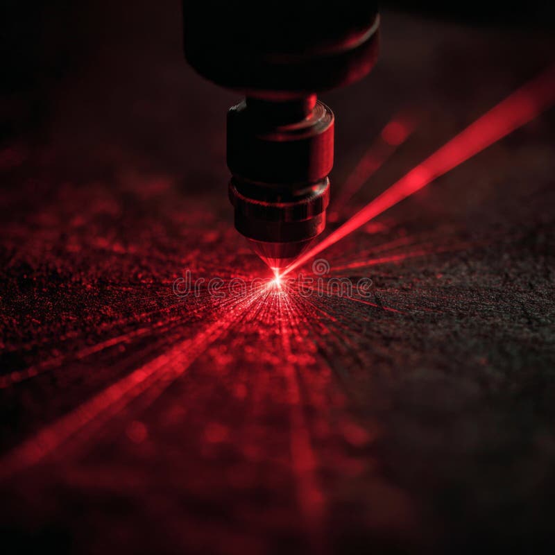
Quality Control and Process Optimization in Laser Beam Machining
Laser Beam Machining (LBM) delivers precision and efficiency but requires stringent quality control to ensure dimensional accuracy, surface integrity, and minimal thermal distortion. Optimization of laser parameters and adaptive strategies further enhances performance, particularly for delicate or high-value materials. This section examines key quality metrics, defect mitigation techniques, and computational tools that enable predictive and real-time adjustments in LBM processes.
Quality Metrics in Laser Beam Machining
Assessing the quality of LBM involves quantifiable parameters that directly impact machined features. Kerf width measures the width of the cut, influenced by laser power, focal position, and material properties. Surface roughness (Ra) evaluates the micro-topography of the machined surface, critical for applications requiring smooth finishes, such as medical implants or optical components. Taper angles indicate the deviation from verticality in the cut walls, often caused by heat accumulation or improper beam focus. These metrics are typically measured using:
Coordinate Measuring Machines (CMMs) for kerf width and taper angles.
Profilometers or optical interferometers for surface roughness (Ra).
Scanning Electron Microscopy (SEM) for high-magnification defect analysis.
Key Formula for Surface Roughness (Ra):
Ra = (1/L) ∫|f(x)| dx, where L is the evaluation length and f(x) is the surface profile deviation from the mean line.
Strategies for Optimizing Laser Parameters to Minimize Heat Distortion
Delicate materials, such as titanium alloys or ceramics, are prone to thermal damage due to localized heating during LBM. Optimizing laser parameters mitigates these effects by balancing energy input and material response. Critical adjustments include:
Pulse Overlap: Reducing overlap between consecutive pulses minimizes heat buildup, particularly in pulsed laser machining. Overlaps of 10–30% are common for achieving clean cuts without excessive thermal stress.
Scanning Speed: Higher speeds reduce dwell time per spot, lowering heat accumulation. However, excessively high speeds may result in incomplete material ablation. Optimal speeds range from 10–1000 mm/s, depending on material thickness and laser wavelength.
Peak Power and Pulse Duration: Shorter pulses (femtosecond to picosecond range) reduce thermal diffusion, making them ideal for heat-sensitive materials. Peak power adjustments (e.g., 10^6–10^12 W/cm²) must align with the material’s ablation threshold.
Assist Gas Pressure: Controlled gas flow (e.g., nitrogen or oxygen) removes debris and cools the kerf, further reducing thermal distortion. Pressures of 5–20 bar are typical for metals, while inert gases like argon prevent oxidation in reactive materials.
Common Defects in Laser Beam Machining and Mitigation Strategies
Defects in LBM arise from suboptimal parameters, material properties, or equipment issues. The following table categorizes defects, their causes, and corrective actions:
| Defect Type |
Possible Causes |
Corrective Actions |
|---|
| Recast Layers |
- Excessive heat input causing material re-melting and solidification on cut edges.
- Insufficient assist gas flow leading to poor debris ejection.
- Improper focal position resulting in uneven energy distribution.
|
- Reduce pulse energy or increase scanning speed to lower heat input.
- Optimize assist gas type (e.g., oxygen for metals, nitrogen for polymers) and pressure.
- Adjust focal position to ensure consistent beam intensity at the workpiece surface.
|
| Dross Formation |
- Incomplete material removal due to low laser power or improper pulse overlap.
- High thermal conductivity materials (e.g., copper) absorbing heat without clean ablation.
- Contaminants or oxide layers on the workpiece surface.
|
- Increase laser power or reduce scanning speed to ensure full penetration.
- Use pre-treatment (e.g., mechanical cleaning or chemical etching) to remove surface oxides.
- Employ hybrid techniques (e.g., laser-assisted machining) for high-reflectivity materials.
|
| Incomplete Cuts or Tapered Edges |
- Improper focal depth or beam divergence affecting energy distribution.
- Material thickness exceeding the laser’s effective penetration depth.
- Thermal stresses causing material deformation during cutting.
|
- Adjust focal length or use a dynamic focus system for varying thicknesses.
- Increase laser power or switch to a higher-wavelength laser (e.g., CO₂ for thicker metals).
- Apply stress-relief treatments post-machining or use adaptive path planning to minimize thermal gradients.
|
| Surface Roughness Exceeding Tolerances |
- High pulse energy causing excessive material ejection and micro-cracks.
- Improper pulse frequency or overlap leading to inconsistent ablation.
- Material grain structure or anisotropy affecting laser-matter interaction.
|
- Reduce pulse energy and increase frequency for finer surface finishes.
- Use adaptive pulse shaping (e.g., variable pulse duration) to match material properties.
- Employ post-machining finishing techniques (e.g., polishing or electrochemical machining).
|
Computational Modeling for Thermal Effect Prediction and Path Optimization
Finite Element Analysis (FEA) and Computational Fluid Dynamics (CFD) simulate thermal gradients, stress distribution, and material ablation during LBM. These models incorporate:
Heat Transfer Equations: Predict temperature distribution using Fourier’s law, accounting for conduction, convection, and radiation losses.
Material-Specific Properties: Thermal conductivity, specific heat, and ablation thresholds (e.g., 10^6–10^9 W/cm² for metals).
Laser-Matter Interaction Models: Multi-physics simulations coupling electromagnetic absorption with phase changes (melting, vaporization).Example Applications:
Aerospace Components: FEA predicts thermal distortion in titanium alloy turbine blades, optimizing laser paths to minimize warping.
Microelectronics: CFD models assist gas flow dynamics in micro-machining, ensuring debris-free cuts in silicon wafers.
Biomedical Implants: Thermal simulations guide parameter selection for stainless steel or cobalt-chrome alloys to prevent hydrogen embrittlement.
Adaptive Control Systems in Real-Time LBM Optimization
Modern LBM systems integrate sensors and machine learning to adjust parameters dynamically, compensating for material inconsistencies or environmental variations. Key adaptive strategies include:
In-Process Monitoring:
Acoustic Emission Sensors: Detect anomalies like cracking or incomplete ablation by analyzing sound waves emitted during machining.
Optical Sensors (e.g., Confocal Microscopy): Measure kerf width and surface quality in real-time, triggering adjustments.
Thermal Cameras: Monitor temperature gradients to prevent overheating in sensitive materials.
Closed-Loop Control Systems:
PID Controllers: Adjust laser power or speed based on feedback from sensors (e.g., maintaining a constant kerf width).
Neural Networks: Train on historical data to predict optimal parameters for new materials or geometries.
Case Study: Adaptive Cutting of Composite Materials
A hybrid system combining CO₂ laser ablation with real-time force sensing adjusts scanning speed when encountering fiber-rich regions in carbon-fiber-reinforced polymers (CFRP). This reduces delamination and extends tool life by 30–40% compared to fixed-parameter methods.
Adaptive Control Algorithm Example (Pseudocode):
```
IF (Surface Roughness > Threshold Ra)
THEN Reduce Pulse Energy by 5%
ELSE IF (Kerf Width < Target ± 5%)
THEN Increase Scanning Speed by 10%
END IF
END IF
```
Laser Beam Machining stands at the intersection of physics, materials science, and automation, offering a transformative solution for modern manufacturing challenges. From its foundational principles—governed by photon absorption and energy conversion—to its material-specific applications and cutting-edge techniques, LBM delivers unmatched precision, efficiency, and flexibility. The integration of advanced systems, real-time optimization, and computational modeling ensures consistent quality while pushing the boundaries of what is achievable in micro and macro-scale fabrication. As industries demand finer tolerances and higher productivity, LBM’s role as a cornerstone of next-generation manufacturing becomes increasingly indispensable, redefining standards for surface finish, structural integrity, and process scalability.
FAQ
what is laser beam machining process?
Q: What exactly is the laser beam machining process and how does it work?
what is ablation in laser beam machining?
Q: How does ablation work in the context of laser beam machining?
|
|

Leave a Comment
Comments are moderated before appearing. The data you submit is processed according to the Privacy Policy of Voltefac.