What Is A Servo Understanding Precision Control Systems
Table of Contents
- Definition and Core Functionality of a Servo in Mechanical and Automated Systems
- Differences Between Servos and Standard Motors
- Internal Components and Their Functional Process
- Types of Servos and Their Applications in Mechanical and Automated Systems
- AC Servos: High-Torque Industrial Automation and Continuous Rotation
- DC Servos: Cost-Effective Precision in Hobbyist and Light Industrial Applications
- Digital Servos: High-Precision Control for Robotics and Advanced Automation
- Performance Comparison: Analog vs. Digital Servos
- How Servos Operate: Control Systems and Feedback
- Closed-Loop Control System Architecture
- Role of Error Signals and PID Controllers
- Feedback Loop Process: Command Input to Motor Adjustment
- Feedback Sensors in Servo Systems
- Servo Mechanics: Gearing, Torque, and Speed
- Gear Ratio Impact on Torque, Speed, and Precision
- Backlash Mitigation in Servo Gearboxes
- Trade-offs Between Continuous Rotation and Positional Servos
- Integration and Programming of Servos
- Wiring and Power Requirements for Servo Integration
- Basic Servo Control Using PWM
- Comparison of Servo Control Libraries
- Advanced Programming Techniques for Multi-Servo Systems
- Servo Selection and Troubleshooting
- Servo Selection Decision Flowchart
- Common Servo Failures and Diagnostic Solutions
- FAQ
- What is a servo motor and how does it work?
- What is a servo motor?
- What is a servo drive?
- What is a servo in Australia?
- What is a servo valve?
- What is a servo in a transmission?
Servos represent a cornerstone of modern automation, enabling precise motion control across industries from robotics to aerospace. Unlike conventional motors, servos integrate feedback mechanisms to achieve sub-millimeter accuracy, making them indispensable in applications where reliability and responsiveness are critical. This system’s ability to dynamically adjust position, speed, and torque in real time distinguishes it as a versatile solution for both industrial-scale operations and hobbyist projects.
The fundamental distinction between a servo and a standard motor lies in its closed-loop architecture, where positional feedback—typically from encoders or potentiometers—continuously corrects deviations from a target command. This interplay of hardware (gearbox, motor, controller) and software (PWM signals, PID algorithms) ensures servos deliver consistent performance under varying loads. Whether deployed in CNC machining, drone stabilization, or collaborative robots, their adaptability stems from a balance of mechanical design and electronic intelligence.

Definition and Core Functionality of a Servo in Mechanical and Automated Systems
Servos function as the precision actuators of modern automation, enabling controlled motion with positional accuracy critical to robotics, CNC machining, and industrial automation. Unlike conventional motors, servos incorporate closed-loop feedback systems, allowing them to dynamically adjust torque and speed to achieve exact angular or linear positioning. Their adaptability stems from integrating positional sensors (e.g., encoders) and proportional control algorithms, ensuring repeatability within fractions of a degree or micrometers. This distinction from standard motors—where output is open-loop and reliant on fixed voltage/speed—positions servos as indispensable components in systems requiring dynamic responsiveness and high precision.
The core functionality of a servo revolves around three interdependent processes: command input, feedback comparison, and error correction. A controller interprets input signals (e.g., PWM pulses) to determine the desired position, while an encoder continuously monitors the actual shaft angle. The difference between these values generates an error signal, which the servo’s electronics use to modulate power to the motor until the discrepancy is nullified. This real-time adjustment capability differentiates servos from standard motors, where positional accuracy depends solely on mechanical stops or external sensors.
Differences Between Servos and Standard Motors
Servos and standard motors (e.g., DC or AC induction motors) serve distinct roles in automation, primarily due to their control mechanisms and feedback integration. While standard motors operate in open-loop configurations—delivering continuous rotation or linear motion based on fixed input voltage—their output lacks inherent positional awareness. In contrast, servos employ closed-loop systems, where feedback from sensors (e.g., optical or magnetic encoders) enables dynamic error correction. This fundamental difference translates to positional accuracy, torque control, and system responsiveness, making servos ideal for applications demanding precision over brute force.The following table summarizes key distinctions between servos and standard motors across functional and application dimensions:
| Servo | Standard Motor | Key Feature | Application Example |
|---|---|---|---|
| Closed-loop control with feedback (encoder/resolver) | Open-loop control (no feedback) | Positional Accuracy | Robotics arm joint positioning (e.g., industrial pick-and-place robots) |
| Variable torque/speed via PWM signal modulation | Fixed torque/speed at given voltage | Dynamic Torque Control | CNC milling machines (adjusting spindle speed for material hardness) |
| Limited rotational range (typically 0–180° or 360° with gearing) | Continuous rotation (360°+ without limits) | Rotational Range | Automotive throttle control (precise angle adjustment for fuel injection) |
| High initial cost but reduced system complexity (integrated feedback) | Lower cost but requires external sensors/controls for precision | System Integration | Drone gimbal stabilization (servos manage camera tilt/pan independently) |
Internal Components and Their Functional Process
A servo’s precision originates from its modular design, where each component contributes to the closed-loop control system. The internal architecture typically includes a DC/AC motor, gearbox, position sensor (encoder/resolver), control circuit (PWM driver), and feedback mechanism. Below is a step-by-step breakdown of their collaborative function:The interplay of these components ensures that a servo can achieve static accuracy (holding a position without drift) and dynamic accuracy (tracking moving targets with minimal lag). For instance, in a 6-axis robotic arm, each servo’s encoder resolves the joint angle to sub-degree precision, enabling the end effector to replicate trajectories with micrometer-level repeatability. This level of control is unattainable with standard motors, which lack inherent feedback and rely on external encoders or limit switches—adding complexity and potential points of failure.
- Motor Core: A high-efficiency DC brushless or AC synchronous motor generates torque proportional to input current. The motor’s design prioritizes low inertia to enhance responsiveness, with permanent magnets or wound stators enabling bidirectional rotation.
- Gearbox: Reduces motor speed while increasing torque output via planetary or spur gears. The gear ratio (e.g., 10:1 to 1000:1) determines the servo’s stall torque and resolution; higher ratios enhance precision but may introduce backlash.
- Position Sensor (Encoder/Resolver):
The sensor’s feedback loop ensures the servo’s actual position matches the commanded setpoint within manufacturer-specified tolerances (e.g., ±0.05°).
- Optical Encoder: Uses slotted disks and photodetectors to count shaft rotations, providing absolute or incremental positional data with resolutions up to 17 bits (120,000 counts/rev).
- Magnetic Resolver: Employs a rotating magnet and stationary coils to output sinusoidal signals, offering robustness in harsh environments (e.g., high temperatures or dust).
- Control Circuit (PWM Driver): Converts input PWM signals (e.g., 1–2 ms pulse width) into proportional voltage/current for the motor. The circuit amplifies the error signal (difference between setpoint and feedback) using PID (Proportional-Integral-Derivative) algorithms to minimize overshoot and settling time.
- Feedback Mechanism: The encoder’s output is digitized and compared against the controller’s reference. The resulting error signal adjusts the motor’s excitation, creating a stable equilibrium at the desired position. High-end servos incorporate field-oriented control (FOC) for brushless DC motors, optimizing torque ripple and efficiency.
Types of Servos and Their Applications in Mechanical and Automated Systems
Servos are classified based on power source, control mechanism, and application requirements, each type offering distinct advantages in torque, speed, and precision. The three primary categories—AC servos, DC servos, and digital servos—serve diverse roles, from high-torque industrial automation to precision hobbyist robotics. Selection depends on factors such as environmental conditions, load demands, and feedback resolution, with trade-offs between analog simplicity and digital sophistication influencing performance. Below, the categorization and real-world applications of each type are examined, alongside comparative performance metrics and niche use cases where specific servo characteristics are critical.AC Servos: High-Torque Industrial Automation and Continuous Rotation
AC (alternating current) servos are designed for heavy-duty applications requiring high torque, continuous rotation, and robust operation in harsh environments. These servos use brushless motors paired with sine-wave or trapezoidal commutation, enabling smooth, high-efficiency motion. Their closed-loop control systems incorporate encoders for precise position feedback, making them ideal for applications where reliability and longevity are paramount.Key applications of AC servos include:
-
Industrial Robotics and Assembly Lines
AC servos power robotic arms in automotive manufacturing (e.g., Tesla’s Gigafactory uses AC servos for battery assembly) due to their ability to handle repetitive, high-torque tasks with minimal wear. Their continuous rotation capability ensures seamless integration into conveyor systems and pick-and-place operations. -
CNC Machining and Metalworking
In CNC mills and lathes (e.g., Haas VF series), AC servos provide the torque necessary for cutting hard materials like titanium or alloy steels. Their closed-loop systems compensate for tool deflection, maintaining precision even under variable loads. -
Packaging Machinery
Beverage filling lines (e.g., Coca-Cola’s automated bottling plants) rely on AC servos for their ability to synchronize multiple axes while handling heavy payloads. Their resistance to thermal drift ensures consistent fill volumes and sealing pressures. -
Aerospace and Defense Systems
AC servos are embedded in flight control surfaces (e.g., Boeing 787’s trailing-edge flaps) and missile guidance systems (e.g., Lockheed Martin’s AGM-176 Griffin) due to their high torque-to-inertia ratio and redundancy in critical applications.
DC Servos: Cost-Effective Precision in Hobbyist and Light Industrial Applications
DC (direct current) servos combine the simplicity of brushed or brushless DC motors with positional feedback, typically via potentiometers or optical encoders. They are favored for applications requiring moderate torque, cost efficiency, and ease of integration. While less powerful than AC servos, DC servos excel in environments where size, weight, and power consumption are constraints, such as consumer electronics and small-scale automation.Key applications of DC servos include:
-
Consumer Robotics and Drones
Hobbyist drones (e.g., DJI’s Mavic series) use DC servos for gimbal stabilization, leveraging their compact size and low power draw. Brushless DC servos in this category often incorporate hall-effect sensors for precise angle control during aerial maneuvers. -
Automotive Steering and Actuation
Electric power steering systems (e.g., Tesla Model 3’s EPS) utilize DC servos for their responsive torque at low voltages. Their ability to provide tactile feedback aligns with driver expectations for steering feel. -
Medical Devices and Prosthetics
Lightweight robotic exoskeletons (e.g., EksoNR’s rehabilitation systems) employ DC servos to assist limb movement. Their low inertia reduces energy consumption, critical for battery-powered medical applications. -
Automated Greenhouse Systems
Precision irrigation and shading systems (e.g., Priva’s greenhouse controllers) use DC servos to adjust motorized blinds and valves. Their cost-effectiveness and compatibility with low-voltage control signals make them ideal for agricultural automation.
Digital Servos: High-Precision Control for Robotics and Advanced Automation
Digital servos represent the evolution of servo technology, integrating microcontrollers, pulse-width modulation (PWM), and high-resolution encoders (e.g., 14-bit or 17-bit feedback) for sub-millisecond response times. They eliminate analog signal limitations by digitizing control inputs, enabling smoother acceleration, higher positioning accuracy, and compatibility with fieldbus protocols (e.g., CANopen, Profibus). Digital servos are the preferred choice in applications demanding real-time adjustments and synchronization across multiple axes.Key applications of digital servos include:
-
Collaborative Robots (Cobots)
Universal Robots’ UR5e cobots deploy digital servos for their force-sensitive gripping and dynamic path planning. The 17-bit encoders ensure repeatability within ±0.02°, critical for human-robot collaboration in shared workspaces. -
Semiconductor Manufacturing Equipment
Wafer handling robots (e.g., Applied Materials’ Endura platforms) use digital servos to position substrates with nanometer precision. Their deterministic latency reduces defects in photolithography processes. -
Autonomous Vehicles and ADAS
Lidar calibration systems (e.g., Velodyne’s HDL-64E) rely on digital servos to rotate sensors at 600 RPM with angular accuracy better than 0.05°. Their closed-loop PID control compensates for vibration-induced errors. -
High-Speed Packaging and Labeling
Digital servos in pharmaceutical packaging (e.g., IMA’s robotic labeling machines) achieve cycle times under 0.5 seconds by synchronizing multiple axes via Ethernet/IP. Their jitter-free motion ensures consistent label placement on irregularly shaped containers.
Performance Comparison: Analog vs. Digital Servos
The trade-offs between analog (traditional DC/AC) and digital servos are critical in system design, particularly in torque, speed, and precision. Below is a comparative analysis structured to highlight operational differences:| Parameter | Analog Servos (DC/AC) | Digital Servos | |||||||||||||||||||||||||||||||||||||||||||||||||||||||||||||||||||||||||||||||||||||
|---|---|---|---|---|---|---|---|---|---|---|---|---|---|---|---|---|---|---|---|---|---|---|---|---|---|---|---|---|---|---|---|---|---|---|---|---|---|---|---|---|---|---|---|---|---|---|---|---|---|---|---|---|---|---|---|---|---|---|---|---|---|---|---|---|---|---|---|---|---|---|---|---|---|---|---|---|---|---|---|---|---|---|---|---|---|---|---|
| Torque Output | Moderate to high (DC: 0.5–10 kg·cm; AC: 5–500 kg·cm). Limited by motor size and cooling constraints. AC servos excel in continuous torque applications, while DC servos are torque-limited at higher speeds. |
High to very high (digital AC: 10–2000 kg·cm; digital DC: 1–50 kg·cm). Enhanced by field-oriented control (FOC) algorithms in brushless designs. Digital AC servos achieve 30–50% higher torque efficiency than analog counterparts due to optimized current profiling. |
|||||||||||||||||||||||||||||||||||||||||||||||||||||||||||||||||||||||||||||||||||||
| Rotational Speed | DC: 3,000–10,000 RPM; AC: 1,500–6,000 RPM. Speed-torque curves degrade at high loads. Analog AC servos maintain speed stability in constant-load applications but suffer from thermal derating. |
DC: 5,000–20,000 RPM; AC: 2,000–10,000 RPM. Digital commutation reduces cogging and allows higher RPM at partial loads. Digital servos in drones achieve 20,000 RPM with <1% speed variation, enabled by real-time sensor fusion. |
|||||||||||||||||||||||||||||||||||||||||||||||||||||||||||||||||||||||||||||||||||||
| Positional Precision | DC: ±0.5°–±2° (potentiometer feedback); AC: ±0.05°–±0.5° (encoder-based). Analog drift affects long-term accuracy. Thermal expansion in analog systems introduces positional errors of up to 0.1° per 10°C in industrial AC servos. |
±0.01°–±0.1° (14–17-bit encoders). Digital filtering and PID tuning eliminate hysteresis.
How Servos Operate: Control Systems and FeedbackServo mechanisms rely on closed-loop control systems to achieve precise positioning and dynamic response in mechanical and automated applications. The core of this functionality lies in the continuous comparison between a desired command input and the actual motor position, adjusted through feedback mechanisms and proportional control algorithms. This section explores the operational principles of servos, focusing on the role of error signals, PID controllers, and pulse-width modulation (PWM) in maintaining accuracy. Additionally, it examines the types of feedback sensors used in servos, their impact on performance, and the fundamental distinction between open-loop and closed-loop systems.The closed-loop architecture of a servo ensures that deviations from the target position are actively corrected, making it indispensable in high-precision applications such as robotics, CNC machining, and aerospace systems. Without feedback, even minor disturbances—such as load variations or mechanical backlash—could lead to significant positioning errors, compromising system reliability. Closed-Loop Control System ArchitectureThe operation of a servo motor is governed by a closed-loop control system, where the actual output (motor position) is continuously monitored and compared to the reference input (desired position). This comparison generates an error signal, which is processed by a controller to adjust the motor’s torque and speed. The system’s stability and responsiveness depend on the efficiency of this feedback loop, which typically involves the following components:1. Command Input: The desired angular position or velocity, provided by a microcontroller, PLC, or human operator. The closed-loop process ensures that the servo compensates for disturbances, such as mechanical friction or external loads, by dynamically recalibrating the motor’s movement. This real-time adjustment is critical in applications requiring sub-millimeter precision, such as medical imaging devices or automated assembly lines. Role of Error Signals and PID ControllersThe error signal is the fundamental metric in closed-loop control, representing the discrepancy between the desired and actual position. Its magnitude and direction dictate the servo’s response through the Proportional-Integral-Derivative (PID) controller, which applies three distinct correction mechanisms:- Proportional (P): Responds to the current error magnitude with a force proportional to its size. A higher P-gain increases responsiveness but may cause overshoot. The PID controller’s output is converted into a PWM signal, which modulates the power supplied to the motor. PWM adjusts the average voltage applied to the motor windings by rapidly switching the signal on and off, effectively controlling torque without excessive heat generation. The duty cycle of the PWM signal (percentage of time the signal is "on") determines the motor’s speed and direction. PID Tuning Considerations: Feedback Loop Process: Command Input to Motor AdjustmentThe closed-loop feedback process can be visualized as a sequential workflow, where each step refines the motor’s position based on real-time data. Below is a structured breakdown of the loop:
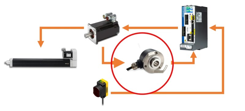
Feedback Sensors in Servo SystemsThe accuracy and reliability of a servo system are directly influenced by the feedback sensor, which provides real-time positional data. Common sensor types include:- Optical Encoders: Use light interruption (incremental) or absolute position encoding (absolute) to achieve high resolution (e.g., 2048–16,384 pulses/revolution). Ideal for dynamic systems requiring precise velocity control. The choice of sensor impacts both performance and cost, as illustrated below:
Backlash Mitigation in Servo GearboxesBacklash—defined as the unintended play or gap between meshing gear teeth—degrades servo performance by introducing positional errors, vibration, and reduced repeatability. In high-precision applications such as CNC machining or surgical robots, backlash can lead to inaccuracies exceeding tolerable limits. Mitigation techniques are categorized into mechanical, design, and control-based strategies.The following steps outline a systematic approach to minimizing backlash in servo gearboxes: 1. Gear Tooth Profile Optimization 2. Preloading and Tensioning 3. Material and Manufacturing Tolerances 4. Electronic Compensation 5. Lubrication and Environmental Controls For applications where backlash cannot be entirely eliminated (e.g., cost-sensitive consumer devices), hybrid approaches—combining mechanical preloading with software compensation—are often adopted. For instance, the Dynamixel MX-series servos use a dual-gear system with built-in backlash compensation algorithms to achieve ±1° accuracy in robotic joints. Trade-offs Between Continuous Rotation and Positional ServosServos are broadly classified into positional servos (fixed-angle operation) and continuous rotation servos (360° unrestricted motion), each optimized for distinct functional requirements. The following blockquote encapsulates the key trade-offs between these two variants:Continuous rotation servos prioritize unrestricted motion at the expense of torque and precision, making them ideal for applications demanding constant rotational movement (e.g., robotic wheels, drone propellers). Their gearboxes lack positional feedback mechanisms, relying instead on open-loop control, which limits accuracy to ±5–10°. In contrast, positional servos excel in high-torque, high-precision tasks by incorporating closed-loop feedback (e.g., optical encoders), enabling sub-degree resolution. However, their fixed operational range (typically 120°–300°) and higher cost restrict their use to scenarios requiring discrete positioning, such as robotic grippers or camera pan-tilt systems. The selection hinges on whether the application prioritizes motion continuity (continuous rotation) or positional accuracy (positional servo), with hybrid systems (e.g., modular servos with detachable gearheads) offering a compromise for versatile automation.In practice, continuous rotation servos are often paired with external gear reducers or custom firmware to simulate positional control, as seen in DIY robotics projects using MG996R servos. Conversely, positional servos can be retrofitted with slip rings or absolute encoders to enable limited continuous rotation, though this increases complexity and cost. For example, the ServoCity S150 positional servo, when combined with a 360° gearhead, achieves a balance between torque (1.5 kg-cm) and rotational range, suitable for automated door systems.
Integration and Programming of ServosServo motors are fundamental components in automated and robotic systems, enabling precise control over angular position, velocity, and acceleration. Their integration with microcontrollers and embedded systems requires adherence to electrical specifications, proper wiring, and programming techniques to ensure reliable operation. This section provides a structured guide on connecting servos to microcontrollers, basic and advanced programming methods, and a comparison of control libraries to facilitate implementation in mechanical and automated applications.Wiring and Power Requirements for Servo IntegrationServo motors require three primary connections to a microcontroller: power (VCC), ground (GND), and control signal (PWM). The wiring process varies based on the servo’s voltage rating (typically 4.8V–6V for standard servos, up to 24V for high-torque variants) and the microcontroller’s capabilities. Below are the key considerations for wiring:- Power Supply: Power Rule: Always connect servo ground (GND) to the microcontroller’s ground to maintain a common reference. Avoid daisy-chaining power sources to prevent noise or instability. - Signal Wiring Best Practices: Example Wiring Diagram (Arduino Uno to Standard Servo): Servo (SG90) | Arduino Uno Basic Servo Control Using PWMServos interpret PWM signals as angular positions via pulse width duration. A standard servo expects:Below is a C++ code snippet for Arduino using the `Servo.h` library to control a servo at a specified angle. Each line is annotated for clarity: #include Servo myServo; // Create a servo object void setup() { void loop() { Key Explanations: Comparison of Servo Control LibrariesSelecting the right library depends on the microcontroller platform, ease of use, and required features. Below is a comparative table of popular servo control libraries:
Advanced Programming Techniques for Multi-Servo SystemsMulti-servo systems (e.g., robotic arms, CNC machines) require synchronization, trajectory optimization, and error correction. Advanced techniques include inverse kinematics, motion profiling, and real-time feedback adjustment. Below are key algorithms and methods:Multi-servo coordination relies on trajectory planning to ensure smooth, collision-free motion. The following algorithms address common challenges: - Inverse Kinematics (IK): Servos exemplify the convergence of mechanical engineering and control theory, offering unparalleled precision in dynamic environments. From selecting the right gear ratio to troubleshooting drift or integrating multi-axis systems, their implementation demands a holistic understanding of torque-speed trade-offs, feedback loops, and environmental resilience. As automation evolves, servos remain the backbone of systems where human-like dexterity meets industrial-grade reliability, bridging the gap between raw mechanical motion and intelligent actuation. A servo motor is a rotary or linear actuator that allows precise control of angular or linear position, speed, and acceleration. It uses feedback (usually from a potentiometer, encoder, or resolver) to adjust its position continuously, matching a desired input signal. Servos are commonly used in robotics, RC models, and industrial automation for tasks requiring exact movement control. A servo motor is an electromechanical device that rotates or moves to a specific angle or position with high accuracy, controlled by an input signal. Unlike standard motors, it includes a feedback mechanism to correct errors and maintain precise positioning. They are widely used in applications like robotics, drones, and automated machinery. A servo drive is an electronic device that powers and controls a servo motor by converting voltage signals into precise motion. It regulates speed, torque, and position based on commands from a controller, often using feedback from encoders. Servo drives are essential in CNC machines, packaging equipment, and other high-precision systems. In Australia, "servo" commonly refers to a service station (gas station) where fuel, automotive services, and sometimes convenience stores are offered. The term originates from the British "self-service" stations, though modern Australian servos often include full-service options. Outside automotive contexts, "servo" still means a servo motor or actuator in technical fields. A servo valve is a precision hydraulic control device that regulates fluid flow direction, pressure, and flow rate to achieve accurate mechanical motion. It uses feedback from a pilot stage to adjust a main spool, enabling rapid and responsive control in heavy machinery like excavators or industrial presses. Servo valves are critical in systems requiring high-speed, high-precision hydraulic actuation. In automotive transmissions, a "servo" typically refers to a servo mechanism that assists with gear shifting by using hydraulic or pneumatic pressure to engage clutches or bands. These servos multiply the force applied by the driver (via the shifter) to ensure smooth, reliable gear changes, especially in older manual transmissions or automatic systems. Modern vehicles may use electronic or hydraulic servos for similar purposes. |

Leave a Comment
Comments are moderated before appearing. The data you submit is processed according to the Privacy Policy of Voltefac.