What Is Electrical Energy Fundamentals Applications
Table of Contents
- Fundamental Principles of Electrical Energy
- Core Concept of Electrical Energy in Physics
- Mathematical Relationships: Voltage, Current, Resistance, and Energy
- Differentiating Electrical Energy from Other Energy Forms
- Calculating Electrical Energy in Real-World Applications
- Sources and Generation of Electrical Energy
- Categorization of Primary Electrical Energy Sources
- Working Principles of Major Power Generation Methods
- Comparative Analysis of Generation Methods
- Energy Conversion Process: Source to Grid Distribution
- Emerging Technologies in Electrical Energy Generation
- Electrical Energy in Circuits and Systems
- Transmission of Electrical Energy in Circuit Configurations
- Role of Passive and Active Components in Energy Dynamics
- Power Loss in Transmission Lines Due to Resistance
- Applications of Electrical Energy
- Categorization of Electrical Energy Applications
- Timeline of Major Milestones in Electrical Energy Applications
- Electrical Energy in Sustainable Solutions
- Safety and Efficiency in Electrical Energy Use
- Safety Guidelines for Electrical Energy Handling and Storage
- Energy Efficiency Measures in Residential and Commercial Settings
- FAQ
- What does the term "energy" specifically refer to in the field of electrical engineering?
- How does an energy meter in electrical systems measure and display energy consumption?
- What is the purpose of an energy audit in electrical engineering, and what does it involve?
- What role does energy play in the context of an electric field?
- How is energy transferred within electrical systems, and what are common methods?
- What qualifies as an energy source in electrical systems, and what are examples?
Electrical energy serves as the invisible force powering modern civilization, enabling everything from household appliances to global communication networks. At its core, this dynamic form of energy arises from the movement of charged particles—primarily electrons—within conductors, transforming potential energy into usable work through voltage, current, and resistance. Unlike mechanical or thermal energy, electrical energy offers unparalleled efficiency in transmission and conversion, making it indispensable in industries, transportation, and sustainable technologies. Understanding its principles not only demystifies everyday devices but also unlocks solutions for energy optimization, safety, and innovation in an increasingly electrified world.
The study of electrical energy bridges theoretical physics with practical engineering, where Ohm’s Law and Joule’s Law quantify its behavior in circuits, while real-world applications—from solar farms to electric vehicles—demonstrate its adaptability. This exploration examines how electrical energy is generated, transmitted, and harnessed, alongside its role in shaping a future where efficiency and sustainability define technological progress. By dissecting its fundamental properties, sources, and systemic applications, we reveal how this fundamental force underpins the infrastructure of contemporary society.

Fundamental Principles of Electrical Energy
Electrical energy represents one of the most versatile and widely utilized forms of energy in modern society, underpinning everything from household appliances to industrial machinery and renewable power systems. At its core, electrical energy arises from the movement of charged particles—primarily electrons—within a conductor or the potential difference between charged bodies. Unlike mechanical or thermal energy, which relies on motion or temperature gradients, electrical energy exploits the fundamental properties of electric fields and charge dynamics to perform work efficiently. This section explores the theoretical foundations of electrical energy, its quantitative relationships with voltage, current, and resistance, and its distinct characteristics compared to other energy forms.Core Concept of Electrical Energy in Physics
Electrical energy is defined as the capacity to perform work due to the presence and motion of electric charges. In a closed circuit, this energy manifests in two primary forms:1. Kinetic Energy of Charges: Electrons in motion (electric current) transfer energy from a source to a load.
2. Potential Energy (Electrostatic): Charges separated by a voltage difference store energy, which is converted into other forms (e.g., light, heat, motion) when released.
The transfer of electrical energy depends on the electric potential difference (voltage, V), the rate of charge flow (current, I), and the opposition to current (resistance, R). These parameters are interconnected through fundamental laws, enabling precise calculations of energy consumption and system design.
Mathematical Relationships: Voltage, Current, Resistance, and Energy
The interplay between voltage, current, and resistance governs electrical energy transfer. Below is a comparative table summarizing key laws and their mathematical expressions, along with unit conversions for practical applications.| Law/Concept | Mathematical Expression | Units | Description |
|---|---|---|---|
| Ohm’s Law | V = I × R |
Voltage (V): Volts (V) Current (I): Amperes (A) Resistance (R): Ohms (Ω) |
Defines the relationship between voltage, current, and resistance in a conductor. Higher resistance reduces current for a given voltage. |
| Joule’s Law (Power Dissipation) | P = I² × R P = V² / R P = V × I |
Power (P): Watts (W) | Describes how electrical energy is converted into heat in a resistor. Power is proportional to the square of current or voltage. |
| Electrical Energy Calculation | E = P × t E = V × I × t E = I² × R × t |
Energy (E): Joules (J) or Watt-hours (Wh) Time (t): Seconds (s) or Hours (h) |
Energy consumed or delivered over time, derived from power multiplied by duration. Unit conversions: 1 Wh = 3600 J. |
Differentiating Electrical Energy from Other Energy Forms
Electrical energy exhibits unique properties that distinguish it from mechanical, thermal, and chemical energy. The following table contrasts these forms across three dimensions: source, transfer mechanism, and practical applications.| Energy Form | Source | Transfer Mechanism | Practical Applications |
|---|---|---|---|
| Electrical Energy | Movement of electrons (current) or stored charge (voltage). Generated via electromagnets, photovoltaics, or chemical reactions (batteries). | Transmitted via conductors (wires) or electromagnetic fields (wireless). Energy loss minimized through high-voltage transmission. | Powering devices (computers, motors), lighting, communication systems, and industrial processes. |
| Mechanical Energy | Kinetic (motion) or potential (position/elevation) energy of objects. | Transferred through physical contact (friction, collisions) or fluid dynamics (hydraulic/pneumatic systems). | Automotive engines, wind turbines, and machinery (e.g., conveyor belts). |
| Thermal Energy | Random motion of molecules (heat). Generated by combustion, friction, or electrical resistance. | Transferred via conduction (solids), convection (fluids), or radiation (electromagnetic waves). | Heating systems, cooking appliances, and waste heat recovery in power plants. |
| Chemical Energy | Stored in molecular bonds (e.g., fossil fuels, batteries). Released via redox reactions. | Converted to other forms (e.g., electrical in batteries, thermal in combustion). | Fuel cells, gasoline engines, and electrochemical storage (lithium-ion batteries). |
Calculating Electrical Energy in Real-World Applications
Electrical energy consumption is quantified in joules (J) or watt-hours (Wh), depending on the context. The following step-by-step procedure demonstrates how to calculate energy for household appliances using practical examples.Prerequisites:
Step-by-Step Procedure:
1. Determine Power (P):
For appliances, power is often labeled (e.g., a 60 W light bulb). If missing, use:
P = V × IExample: A laptop charger supplies 19 V at 3.16 A. Power = 19 V × 3.16 A = 60.04 W.
2. Convert Time to Consistent Units:
Ensure time is in hours for Wh or seconds for J.
Example: A microwave operates for 10 minutes (0.167 h) or 600 s.
3. Calculate Energy (E):
Use the formula:
E (Wh) = P (W) × t (h)
E (J) = P (W) × t (s)Example 1 (Wh): A 100 W bulb used for 5 hours consumes:
E = 100 W × 5 h = 500 Wh (or 500 × 3600 J = 1,800,000 J).
Example 2 (J): A 2.5 kW (2500 W) electric heater running for 30 minutes (1800 s) consumes:
E = 2500 W × 1800 s = 4,500,000 J.
4. Unit Conversions for Practicality:
Example: 500 Wh = 0.5 kWh.
*
Sources and Generation of Electrical Energy
Electrical energy is derived from various primary sources, each characterized by distinct environmental interactions, technological maturity, and scalability. The generation process transforms raw energy—whether from fossil fuels, nuclear reactions, or renewable resources—into usable electricity through specialized conversion systems. This section examines the categorization of energy sources, their operational principles, and comparative analyses of traditional and emerging technologies to assess their role in modern power grids.Categorization of Primary Electrical Energy Sources
Primary sources of electrical energy are broadly classified into renewable and non-renewable categories, each with unique implications for sustainability, resource depletion, and environmental impact.Renewable Sources leverage naturally replenishing processes and include:
Non-renewable Sources rely on finite reserves and are associated with higher carbon emissions and long-term depletion risks:
Environmental Impacts by Source Category
- Renewable Sources
- Solar: Minimal operational emissions but requires rare materials (e.g., silicon, silver) for PV panels, with land-use conflicts in large-scale installations.
- Wind: Low carbon footprint; however, avian and bat mortality risks, noise pollution, and visual impacts in onshore projects.
- Hydropower: Disrupts aquatic ecosystems, alters river flows, and emits methane from submerged biomass in reservoirs.
- Non-renewable Sources
- Coal: Highest CO₂ emissions per kWh (~820–1,000 g CO₂/kWh), alongside sulfur dioxide (SO₂) and particulate matter, contributing to respiratory diseases and acid rain.
- Natural Gas: Lower emissions than coal (~490–590 g CO₂/kWh) but still releases methane (a potent greenhouse gas) during extraction and leaks.
- Nuclear: Produces minimal CO₂ but generates long-lived radioactive waste requiring secure storage; risks of catastrophic accidents (e.g., Chernobyl, Fukushima).
Working Principles of Major Power Generation Methods
The conversion of primary energy into electrical energy follows distinct physical and chemical processes, optimized for efficiency and scalability. Below are three dominant methods, analyzed for their operational mechanics and comparative performance.Thermal Power Generation (Fossil/Nuclear)
Thermal plants generate electricity by converting heat into mechanical energy via steam turbines, followed by electrical conversion using generators. The process involves:
1. Fuel Combustion/Reaction: Coal, gas, or nuclear fission heats water to produce high-pressure steam.
2. Turbine Rotation: Steam expands through turbine blades, converting thermal energy into rotational kinetic energy.
3. Electrical Conversion: A coupled generator converts mechanical rotation into alternating current (AC) via electromagnetic induction.
Key Efficiency Factor:Hydroelectric Power Generation
Thermal efficiency (η) is defined as:
η = (Net Electrical Output / Heat Input) × 100%
Modern combined-cycle gas plants achieve ~60% efficiency, while coal plants typically range between 30–45%.
Hydropower exploits the gravitational potential energy of water stored in reservoirs or flowing rivers. The process includes:
1. Water Storage/Diversion: Dams regulate water flow to maintain consistent pressure.
2. Turbine Activation: Water passes through turbines (e.g., Francis, Kaplan), transferring energy to the rotor.
3. Generator Operation: Mechanical energy from the turbine spins a generator, producing AC electricity.
Photovoltaic (Solar) Power Generation
PV systems directly convert sunlight into electricity using the photovoltaic effect, where semiconductor materials (e.g., silicon) generate electron-hole pairs upon photon absorption. The process entails:
1. Photon Absorption: Sunlight strikes PV cells, exciting electrons in the semiconductor.
2. Charge Separation: Built-in electric fields (via p-n junctions) direct electrons to create a voltage.
3. DC-to-AC Conversion: Inverters transform DC output into grid-compatible AC power.
Comparative Analysis of Generation Methods
The following table summarizes key performance metrics for thermal, hydroelectric, and photovoltaic systems, including efficiency, levelized cost of energy (LCOE), and scalability. Data sources include IRENA (2020), U.S. EIA (2021), and NREL (2022).| Metric | Thermal (Coal/Gas) | Hydroelectric | Photovoltaic |
|---|---|---|---|
| Efficiency (%) | 30–60 (combined-cycle gas) | 70–90 (large-scale) | 15–22 (utility-scale) |
| LCOE (USD/kWh) | 0.05–0.15 (coal), 0.03–0.07 (gas) | 0.03–0.10 (varies by region) | 0.03–0.06 (utility-scale) |
| Scalability | High (centralized plants) | Moderate (geographical constraints) | High (distributed rooftop/utility-scale) |
| Operational Flexibility | Moderate (ramp-up/down times) | Low (dependent on water flow) | Low (intermittent output) |
| Environmental Footprint | High (emissions, water use) | Moderate (ecosystem disruption) | Low (post-installation) |
Energy Conversion Process: Source to Grid Distribution
The transformation of primary energy into distributed electrical power involves multiple intermediate steps, each optimized for efficiency and reliability. The following flowchart annotations describe the sequential stages:1. Energy Source Activation
2. Mechanical Energy Conversion
3. Electrical Generation
4. Grid Integration
Critical Components in Conversion Process:
Steam Turbines: Convert thermal energy to mechanical work (η ~35–45% for coal). Inverters (PV Systems): Ensure grid synchronization with anti-islanding protection. Transformers: Minimize transmission losses via voltage regulation (e.g., 10 kV to 400 kV).
Emerging Technologies in Electrical Energy Generation
Advancements in renewable and alternative energy technologies aim to address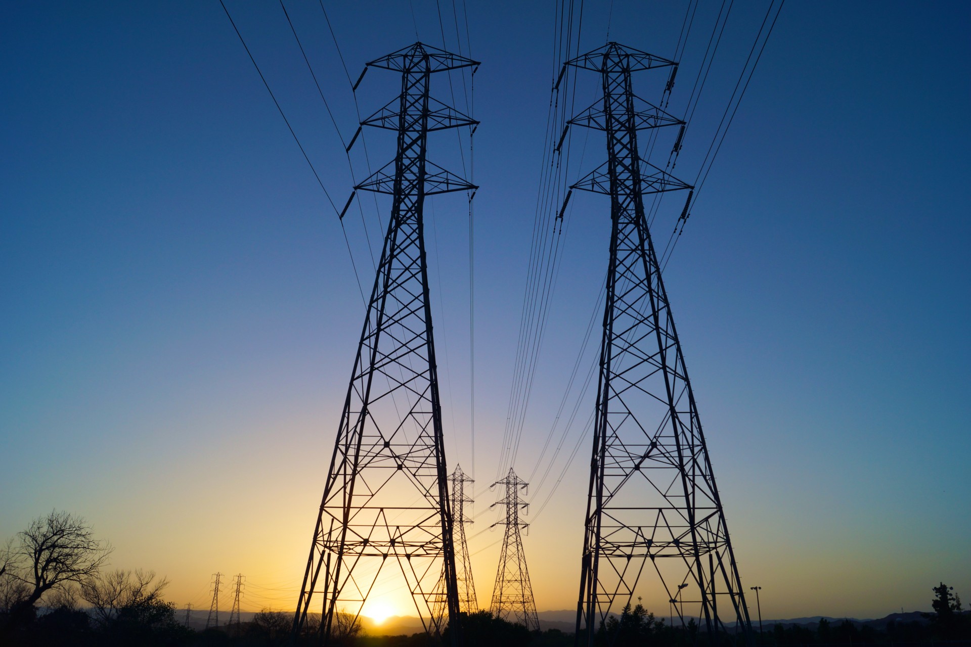
Electrical Energy in Circuits and Systems
Electrical energy transmission and distribution in circuits and systems form the backbone of modern power infrastructure, where efficiency, configuration, and component behavior determine performance. Circuits serve as pathways for energy flow, governed by fundamental laws such as Ohm’s, Kirchhoff’s, and Joule’s, which dictate how voltage, current, and resistance interact. The arrangement of components—whether in series, parallel, or hybrid configurations—directly influences power dissipation, energy storage, and system reliability. Understanding these dynamics is critical for designing scalable systems, minimizing losses, and optimizing energy conversion in applications ranging from microelectronics to high-voltage grids.Transmission of Electrical Energy in Circuit Configurations
Electrical energy propagates through circuits via conductive paths where voltage drives current, subject to resistive, capacitive, or inductive impedances. The configuration of components—series, parallel, or mixed—dictates how total resistance, voltage division, and current distribution behave, thereby affecting power delivery and system stability.Series Circuits
In a series configuration, components are connected end-to-end, forming a single path for current flow. Key characteristics include:
Example: A series circuit with three resistors (10Ω, 20Ω, 30Ω) and a 60V source yields I = 1A, Vtotal = 60V, and Ptotal = 60W, with individual power losses of 10W, 20W, and 30W respectively.
Parallel Circuits
Parallel configurations connect components across common voltage nodes, creating multiple current paths. Key characteristics include:
Example: Three parallel resistors (10Ω, 20Ω, 30Ω) with a 60V source yield Itotal = 9A, Ptotal = 540W, and individual currents of 6A, 3A, and 2A.
Mixed Circuits
Combining series and parallel segments allows tailored designs for specific applications, such as voltage regulation or current amplification. Analysis requires applying Kirchhoff’s laws to identify equivalent resistances and node voltages.
Role of Passive and Active Components in Energy Dynamics
Components in circuits either store, dissipate, or convert electrical energy, with passive elements passively responding to applied signals and active elements modifying behavior dynamically. Below is a comparative table of key components, their symbols, functions, and energy roles:| Component Type | Symbol | Function | Energy Role | Key Equation |
|---|---|---|---|---|
| Passive Components | Impedes current flow proportionally to resistance. | Dissipates energy as heat (Joule heating). | P = I²R = V²/R |
|
| Stores energy in an electric field when charged. | Temporarily stores and releases energy; filters AC signals. | E = ½CV² |
||
| Opposes changes in current via magnetic field generation. | Stores energy magnetically; smooths current fluctuations. | E = ½LI² |
||
| Active Components | Allows current in one direction only (rectification). | Converts AC to DC; protects circuits from reverse polarity. | Vout ≈ Vin – Vdrop (forward bias) |
|
| Amplifies or switches electronic signals via current control. | Converts low-power signals to high-power outputs; enables logic operations. | IC = βIB (for BJT in active mode) |
||
| Amplifies voltage difference between inputs with high gain. | Signal conditioning, filtering, and analog computation. | Vout = AOL(V+ – V–) |
Power Loss in Transmission Lines Due to Resistance
Transmission lines incur resistive losses (I²R), which degrade efficiency, especially over long distances. The percentage loss depends on line resistance, current, and power factor, with high-voltage transmission mitigating losses via reduced current for the same power (P = VI).Key Factors Affecting Loss:
Step-by-Step Loss Calculation:
1. Determine Line Parameters:
R = 2ρL/A(factor of 2 accounts for go-and-return paths).
I = P/V.
Ploss = I²R.
%Loss = (Ploss/P) × 100.
Real-World Example: Long-Distance Power Grid
Applications of Electrical Energy
Electrical energy serves as the backbone of modern civilization, enabling diverse applications across industries, infrastructure, and daily life. From powering essential services to driving technological innovation, its versatility stems from efficiency, controllability, and scalability. This section explores key sectors where electrical energy is indispensable, traces its evolutionary milestones, and examines its role in sustainability and digital infrastructure.Electrical energy’s adaptability is evident in its integration into systems requiring precision, mobility, or high-performance computing. Advancements in energy storage, grid management, and renewable integration further expand its applications, aligning with global demands for efficiency and environmental stewardship. Below, applications are categorized by industry, with use cases illustrating energy demands, technological dependencies, and societal impacts.
Categorization of Electrical Energy Applications
Electrical energy applications span residential, industrial, commercial, and transportation sectors, each with distinct energy requirements and operational constraints. The following categories highlight critical domains where electrical energy drives functionality, productivity, and innovation.1. Lighting Systems
Lighting accounts for ~15% of global electricity consumption, with advancements reducing energy demands by 75% through LED technology (IEA, 2021). Applications range from ambient illumination to specialized industrial or medical lighting, where spectral output and intensity are tailored to tasks.
Energy Requirements:2. Computing and Data Processing
Residential: 10–50 W per fixture (LEDs); 60–100 W (incandescent). Industrial: 100–500 W (high-bay LEDs); UV/IR for curing or sterilization (up to 1 kW). Street Lighting: 50–200 W (solar-powered LEDs reduce grid dependency by 90% in off-grid areas).
Data centers consume ~1–1.5% of global electricity, with cooling and power delivery accounting for 40–50% of operational costs (Uptime Institute, 2022). Electrical energy enables high-performance computing (HPC), cloud services, and AI workloads, where reliability and latency are critical.
Key Systems:3. Transportation Electrification
Servers: 500 W–5 kW per rack; liquid cooling reduces energy use by 30–40%. Network Infrastructure: Routers/switches draw 200–2,000 W; PoE (Power over Ethernet) supplies up to 90 W per port. Backup Power: UPS systems provide 5–30 minutes of runtime (e.g., 10 kVA UPS for 50 servers).
Electric vehicles (EVs) and rail systems rely on electrical energy for propulsion, with battery efficiency improving from ~90 Wh/km (2010) to ~150 Wh/km (2023) (BloombergNEF). Grid-to-vehicle (G2V) and vehicle-to-grid (V2G) integration further optimize energy flows.
Energy Metrics:4. Medical Devices and Healthcare
Passenger EVs: 15–25 kWh/100 km (Tesla Model 3); fast charging at 150–350 kW. Electric Trains: 10–30 MW per unit (e.g., Japan’s Shinkansen); regenerative braking recovers 20–30% energy. E-Aircraft: 500 kW–1 MW for short-haul flights (e.g., Eviation Alice).
Medical applications demand uninterruptible power with strict voltage/frequency stability. Electrical energy powers life-support systems, diagnostic equipment, and surgical tools, where failures risk patient safety.
Critical Systems:5. Industrial Automation and Manufacturing
ICU Equipment: Ventilators (200–500 W); defibrillators (10–50 W). Imaging: MRI machines (15–30 kW); CT scanners (50–100 kW). Surgical Robots: Da Vinci System draws 1.5–2 kW; requires redundant power supplies.
Electrical energy drives motors, robotics, and process control in sectors like automotive, semiconductor fabrication, and food processing. Energy efficiency in Industry 4.0 reduces costs by 20–40% through smart sensors and predictive maintenance.
Process-Specific Requirements:6. Renewable Energy Integration
Motor Systems: 0.75–1,000 kW (e.g., 3-phase induction motors in conveyors). Welding: 200–1,000 A at 20–100 V (MIG/TIG processes). Semiconductor Fabs: Cleanrooms require 1–10 MW; photolithography tools use 5–20 kW.
Electrical energy enables the conversion, storage, and distribution of renewable sources. Solar photovoltaic (PV) and wind systems require inverters (95–98% efficiency) and grid-tied solutions to manage intermittency.
System Specifications:
Solar PV: 3–5 kW residential systems; utility-scale farms (100 MW+). Wind Turbines: 2–15 MW per turbine; grid connection at 69–380 kV. Energy Storage: Lithium-ion batteries (1–100 MWh); pumped hydro (1–3 GW).
Timeline of Major Milestones in Electrical Energy Applications
The evolution of electrical energy applications reflects technological breakthroughs and societal shifts. Below is a chronological overview of pivotal developments, categorized by innovation phase:-
1879–1900: Foundational Era
- 1879: Thomas Edison’s incandescent bulb (40 W) enables residential lighting; first power plants (e.g., Pearl Street Station, 1882) supply 120 V DC.
- 1888: Nikola Tesla’s AC induction motor and George Westinghouse’s AC transmission system (60 Hz) establish modern grids.
- 1891: First hydroelectric plant (Niagara Falls) generates 50 Hz AC for industrial use.
-
1900–1950: Industrialization and Electrification
- 1903: First electric streetcar systems (e.g., Boston) replace horse-drawn transport.
- 1920s–1930s: Rural Electrification Administration (REA) brings power to 90% of U.S. farms; household appliances (refrigerators, radios) proliferate.
- 1936: First nuclear reactor (Chicago Pile-1) lays groundwork for nuclear power.
- 1947: Transistor invention (Bell Labs) enables smaller, more efficient electronic devices.
-
1950–2000: Digital and Automation Revolution
- 1956: First commercial nuclear power plant (Calder Hall, UK) enters operation.
- 1969: ARPANET (precursor to the internet) uses electrical power for data transmission.
- 1970s: Microprocessors (Intel 4004, 1971) reduce computing energy use by orders of magnitude.
- 1980s: Programmable logic controllers (PLCs) automate industrial processes; first EVs (e.g., GM EV1, 1996) emerge.
- 1990s: Smart grids pilot in Sweden and Japan; LED development begins (Nichia Corp., 1993).
-
2000–Present: Smart and Sustainable Systems
- 2007: Tesla Roadster (first highway-legal EV) and Apple’s iPhone (lithium-ion battery) redefine mobility and computing.
- 2010: Smart meters and IoT devices enable real-time energy monitoring; Google’s data centers adopt liquid cooling.
- 2015: Paris Agreement accelerates renewable integration; solar PV costs drop below $0.06/kWh.
- 2020s: V2G technology (e.g., Nissan’s bidirectional chargers), AI-driven grid optimization, and quantum computing (IBM’s 127-qubit processor) push energy-efficient limits.
Electrical Energy in Sustainable Solutions
Sustainability hinges on electrical energy’s role in reducing carbon footprints, optimizing resource use, and enabling circular economies. Key applications include electrified transportation, decentralized energy systems, and intelligent consumption models.1. Electric Vehicles and Smart Charging
EVs reduce lifecycle emissions by 50–70% compared to internal combustion engines (ICCT, 2021). Smart charging algorithms balance grid load by adjusting power draw during low-demand periods (e.g., vehicle-to-home (V2H) systems).
Energy Efficiency
Safety and Efficiency in Electrical Energy Use
Electrical energy systems, while indispensable in modern infrastructure, pose significant risks if not managed with strict adherence to safety protocols and efficiency best practices. Proper handling of high-voltage systems, fault mitigation, and energy optimization are critical to preventing hazards such as electric shocks, fires, and equipment degradation. This section outlines technical guidelines for safe electrical operations, efficiency enhancement strategies, and diagnostic protocols for hazard detection, alongside a comparative analysis of energy storage technologies for off-grid applications.
Safety Guidelines for Electrical Energy Handling and Storage
Safety in electrical systems depends on systematic adherence to technical standards, proper insulation, and protective measures against fault conditions. High-voltage systems, fault currents, and inadequate insulation are primary contributors to electrical accidents. The following guidelines provide structured precautions with technical specifications to mitigate these risks.
- High-Voltage System Handling
High-voltage systems (typically ≥1,000V AC or ≥1,500V DC) require specialized protective equipment and procedures to prevent arcing, flashovers, and electrocution.
- Personal Protective Equipment (PPE): Use insulated gloves (ASTM D120-19, Class 00 for ≤50V, Class 4 for ≥17,000V), arc-rated clothing (NFPA 70E, Category 2 for 8 cal/cm² exposure), and safety glasses with side shields (ANSI Z87.1-2020).
Key Specification: Insulated tools must be tested annually per IEEE 382-2018 for dielectric strength (minimum 100V/mm for low-voltage tools).- Isolation and Lockout-Tagout (LOTO): De-energize circuits using disconnect switches (NEC 240.55) and verify with voltage testers (CAT III/IV, per IEC 61010-1). Apply locks/tags per OSHA 1910.147 to prevent unauthorized re-energization.
Critical Step: Perform a "dead-front" test (visual and instrument confirmation) before working on live parts in high-voltage systems (IEEE 3007.1-2018).- Clearance Distances: Maintain minimum approach distances (MAD) as per NFPA 70E Table 130.4(D):
Voltage Range (kV) MAD (Inches) PPE Category 1–2 12 2 7–15 24 3 38–72 36 4 - Fault Current Management
Fault currents exceeding circuit breaker ratings can cause explosive failures. Use time-current curve coordination (IEEE C37.16-2019) to select protective devices.
- Circuit Breaker Selection: Choose breakers with interrupting ratings ≥3× the available fault current (e.g., 20kA for a 50kA fault). For low-voltage systems, use molded-case breakers (UL 489) with instantaneous trip settings.
Formula: Ifault = (VLL × 1000) / (Zsystem + Zcable) Where Zsystem = 0.1Ω (typical), Zcable = 0.01Ω/km (copper).- Grounding Systems: Implement solid grounding (TT system) for low-voltage systems (<1kV) with ground fault circuit interrupters (GFCIs) per NEC 250.130. For high-voltage, use high-resistance grounding (HRC) to limit fault currents (IEEE 3007.1-2018).
- Insulation and Environmental Controls
Insulation degradation (due to heat, moisture, or chemical exposure) is a leading cause of electrical faults. Select materials based on system voltage and environmental conditions.
- Insulation Classes:
Class Max Temp (°C) Applications A 105 PVC cables, low-voltage motors F 155 Epoxy resins, high-voltage transformers H 180 Polyimide films, aerospace wiring - Moisture and Corrosion Prevention: Use moisture-resistant cables (e.g., XLPE-insulated per IEC 60502) and seal terminations with silicone grease (NEMA TC-1). Monitor insulation resistance with megohmmeters (minimum 1MΩ/V for low-voltage systems).
Energy Efficiency Measures in Residential and Commercial Settings
Energy efficiency reduces operational costs and environmental impact by optimizing power consumption without compromising performance. Key strategies include power factor correction, LED lighting, and high-efficiency appliances, with measurable reductions in energy demand. The following comparisons illustrate typical energy savings before and after implementation.
- Power Factor Correction (PFC)
Inductive loads (e.g., motors, transformers) cause lagging power factors, increasing apparent power and utility penalties. PFC improves efficiency by reducing reactive power (Q) and aligning voltage/current phases.
- Methods and Savings:
Method Initial PF Corrected PF Energy Savings (%) Payback Period (Years) Capacitor Banks 0.65 0.95 15–25% 1–3 Active PFC (Electronic) 0.50 0.99 30–40% 3–5 Synchronous Condensers 0.70 0.98 20–30% 4–6 Formula: Preal = S × PF, where S = √(P2 + Q2).- Implementation Steps:
- Measure PF using a power analyzer (e.g., Fluke 435-II).
- Calculate required kVAR for correction: Qcorrection = P
Electrical energy stands as a cornerstone of human advancement, seamlessly integrating into every facet of modern life while presenting ongoing challenges in generation, distribution, and sustainability. From the precise calculations governing household appliances to the large-scale transformations in renewable energy systems, its versatility ensures continuous innovation. As technologies evolve—such as smart grids, energy storage solutions, and high-efficiency transmission—electrical energy remains pivotal in addressing global demands for reliability, cost-effectiveness, and environmental responsibility. Mastering its principles empowers industries, policymakers, and individuals to harness its potential responsibly, ensuring a future where energy efficiency and accessibility drive progress without compromise.
FAQ
What does the term "energy" specifically refer to in the field of electrical engineering?
In electrical engineering, energy refers to the capacity to do work, measured in joules (J) or watt-hours (Wh), and is the product of power (watts) multiplied by time. It quantifies the total electrical work done by systems like generators, motors, or circuits, distinguishing it from instantaneous power flow.
How does an energy meter in electrical systems measure and display energy consumption?
An energy meter (or electricity meter) is a device that records the total electrical energy supplied to a circuit or consumer, typically in kilowatt-hours (kWh). It integrates power over time, often using electromechanical or digital components, to provide readings for billing or monitoring usage.
What is the purpose of an energy audit in electrical engineering, and what does it involve?
An energy audit in electrical engineering systematically evaluates energy use in buildings or systems to identify inefficiencies, waste, or cost-saving opportunities. It involves measuring equipment performance, analyzing consumption patterns, and recommending upgrades like insulation, lighting, or motor efficiency improvements.
What role does energy play in the context of an electric field?
In an electric field, energy is associated with the potential to move electric charges (voltage) and the work required to separate or assemble charges. Stored energy in a capacitor, for example, is proportional to the field’s strength (E) and the volume it occupies, calculated as (1/2)εE² per unit volume.
How is energy transferred within electrical systems, and what are common methods?
Energy transfer in electrical systems occurs through the movement of electric charge (current) in conductors, driven by voltage differences. Common methods include transmission via power lines (AC/DC), inductive coupling (transformers), or capacitive transfer, with efficiency depending on resistance, frequency, and system design.
What qualifies as an energy source in electrical systems, and what are examples?
An energy source in electrical systems is any device or system that converts stored or natural energy into electrical energy. Examples include generators (mechanical → electrical), solar panels (light → electricity), batteries (chemical → electrical), and fuel cells, which provide the power input for circuits or grids.
Leave a Comment
Comments are moderated before appearing. The data you submit is processed according to the Privacy Policy of Voltefac.